
Extended contact area for leadframe strip testing

A lead frame, lead technology, applied in the direction of semiconductor/solid state device testing/measurement, etc., can solve problems such as problems, lead frame strip testing cannot be performed, etc.

Active Publication Date: 2018-06-26
INFINEON TECH AG
View PDF3 Cites 0 Cited by
  • Summary
  • Abstract
  • Description
  • Claims
  • Application Information

AI Technical Summary

Problems solved by technology

Severing the leads along the final lead outline of the cell leadframe limits the amount of contact area available for probing the leads, which is critical for leadless and short-lead packages with very small lead contact areas inside the final lead outline for probing particularly problematic
Many of these packages are rated for high current operation, but conventional leadframe strip testing often cannot be performed at such high current limitations due to the small contact area available to probe the leads

Method used


Image

  • Extended contact area for leadframe strip testing
  • Extended contact area for leadframe strip testing
  • Extended contact area for leadframe strip testing

Examples


Embodiment Construction

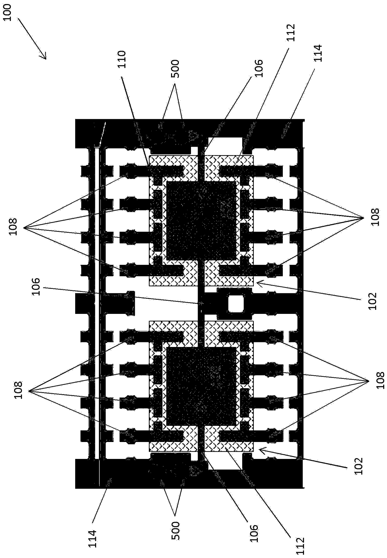
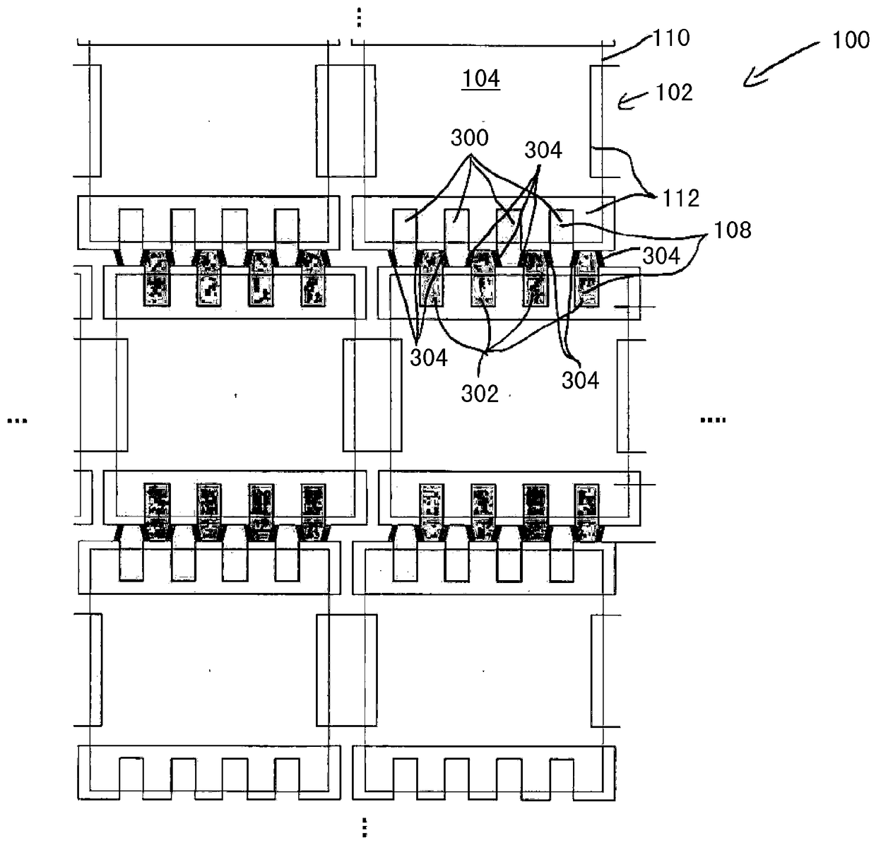
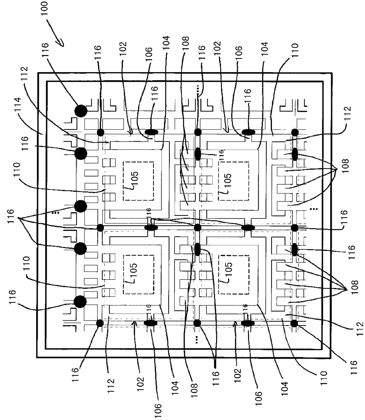
[0017] According to embodiments described herein, a leadframe strip includes a plurality of unit leadframes. At least the leads of the unit leadframe are electrically isolated from the perimeter of the leadframe strip prior to strip testing. After being electrically isolated from the perimeter of the leadframe strip, at least some of the leads extend uninterrupted beyond the final lead outline of the cell leadframe. Leads that extend uninterrupted beyond the final lead profile of the cell lead frame after the electrical isolation process have additional contact areas for test probing. In some cases, portions of the leads that extend uninterrupted beyond the final lead profile of the cell leadframe after the electrical isolation process are actually probed during the testing process. In other cases, leads with extended contact areas remain integrally connected to die paddles of adjacent cell leadframes during the testing process so that adjacent die paddles, rather than the le...


PUM


Abstract

Extended contact area for leadframe strip testing. The leadframe strip includes a plurality of unit leadframes connected to a periphery of the leadframe strip, each unit leadframe having a die tread, a plurality of leads, and a semiconductor die attached to the die tread. The leadframe strips are tested by electrically isolating at least the leads from the perimeter of the leadframe strip such that at least some of the leads extend uninterrupted beyond the final lead profile of the unit leadframe after being electrically isolated from the perimeter of the leadframe strip. Testing the semiconductor die, which includes probing the die pads and leads that extend uninterrupted beyond the final lead profile of the cell lead frame after being electrically isolated from the perimeter of the lead frame strip. The cell lead frame is severed from the lead frame strip along the final lead profile of the cell lead frame after testing the semiconductor die.

Description

technical field [0001] This application relates to leadframe strips, and more particularly to leadframe strip testing. Background technique [0002] The leadframe forms the base or frame of the IC package, providing mechanical support for the semiconductor die during assembly into the finished package. A leadframe typically includes a die paddle for attaching the semiconductor die and leads that provide means for external electrical connections to the die. The die may be connected to the leads by wires (eg, by wire bonding or tape automated bonding). Leadframes are typically constructed from a flat sheet of metal, eg by stamping or etching. The metal sheet is typically exposed to a chemical etchant that removes areas not covered by photoresist. After the etching process, the etched frames are singulated (separated) into leadframe strips. Each leadframe strip includes a plurality of unit leadframes, each having the die paddle and lead structures described above. [0003]...

Claims


Application Information

Patent Timeline
Patent Type & Authority Patents(China)
IPC IPC(8): H01L21/66
CPCH01L22/14H01L2224/97H01L22/32H01L21/78
Inventor 邱尔万林丽叶陈天山
Owner INFINEON TECH AG
Learn More