Hay Grinder

A forage grinder and crushing chamber technology, applied in grain processing, etc., can solve problems such as poor crushing effect, achieve good crushing effect, improve utilization rate, increase or decrease the effect of hammer blades and air chambers

Active Publication Date: 2018-09-28
黄宗瑞
View PDF7 Cites 0 Cited by
  • Summary
  • Abstract
  • Description
  • Claims
  • Application Information

AI Technical Summary

Problems solved by technology

[0003] The purpose of the present invention is to provide a forage pulverizer, which overcomes the defect of poor pulverization effect in the prior art, and has the advantages of thorough pulverization and high pulverization efficiency

Method used


Image

  • Hay Grinder
  • Hay Grinder

Examples


Embodiment 1

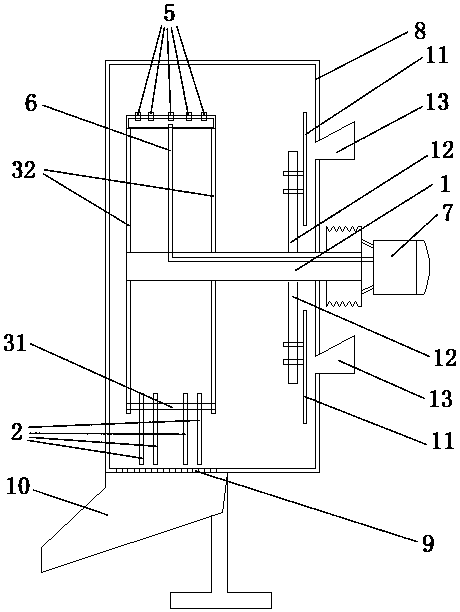
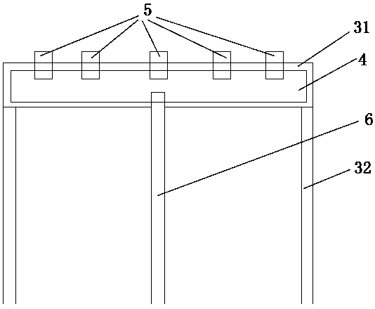
[0023] like Figure 1-2 As shown, the forage pulverizer provided in this embodiment includes a rotating shaft 1, a hammer 2, a hammer frame, an air cavity 4, an air nozzle 5, an air duct 6, a blower 7 and a pulverizing chamber 8. The rotating shaft 1 Penetrating into the crushing chamber 8 from the outside, the hammer frame is arranged on the rotating shaft 1 in the crushing chamber 8; the hammer frame is provided with two mounting pieces 31, and the mounting pieces 31 are parallel to the axis of the rotating shaft 1 One mounting piece 31 is provided with an air cavity 4, the outer end surface of the mounting piece 31 provided with the air cavity 4 is provided with a gas nozzle 5, and the other mounting piece 31 is provided with a hammer perpendicular to the axial direction of the rotating shaft 1. Sheet 2; the air nozzle 5 is communicated with the air cavity 4; the air cavity 4 is communicated with the blower 7 arranged outside the pulverizing chamber 8 through the air condui...


PUM


Abstract

The invention aims at providing a forage pulverizer which comprises a rotating shaft, a hammer slice, a hammer slice frame, an air cavity, an air nozzle, an air guide pipe, an air blower and a pulverizing chamber. The rotating shaft penetrates in the pulverizing chamber from the outside. The hammer slice frame is arranged on the part, arranged in the pulverizing chamber, of the rotating shaft. The hammer slice frame is provided with two or more installation pieces which are parallel to the axial direction of the rotating shaft. The air cavity is formed in at least one installation piece. The air nozzle is arranged on the outer end face of the installation piece provided with the air cavity. At least one installation piece is provided with the hammer slice perpendicular to the axial direction of the rotating shaft. The air nozzle is communicated with the air cavity. The air cavity is communicated with the air blower through the air guide pipe, wherein the air blower is arranged outside the pulverizing chamber. A screen is arranged at the bottom of the pulverizing chamber, and the pulverizing chamber is communicated with a discharging port of the forage pulverizer through the screen. The forage pulverizer overcomes the defect that the pulverizing effect in the prior art is poor, and has the beneficial effects of being simple in structure, rapid and convenient to use, thorough in pulverization and high in pulverizing effect.

Description

technical field [0001] The invention relates to the field of forage processing machinery, in particular to a forage pulverizer. Background technique [0002] Commonly used forage pulverizers are equipped with high-speed rotating rotors in the casing, one is a claw rotor and the other is a hammer rotor. They use claw teeth or touted functions to pulverize the forage. The material of the pulverizer rotates with the rotor driven by the airflow and the blowing force of the rotor, which reduces the relative speed and thus reduces the blowing intensity. The particles are inside, which is not conducive to hitting and crushing again, but also blocks the sieve holes and reduces the separation effect. Therefore, it is of great significance to develop a pulverizing machine with outstanding pulverizing effect. SUMMARY OF THE INVENTION [0003] The present invention aims to provide a forage pulverizer, which overcomes the defects of poor pulverizing effect in the prior art and has th...

Claims


Application Information

Patent Timeline
Patent Type & Authority Patents(China)
IPC IPC(8): B02C18/14B02C13/02B02C23/26B02C23/28
Inventor 李良策杨宏新陈永飘
Owner 黄宗瑞
Why Eureka
Try Eureka