
Buffer block oiling tooling

A buffer block and oiling technology, applied in the field of tooling and fixtures, can solve the problems of poor oiling effect, difficult control of oil quantity, uneven oil application, etc., and achieve good oiling effect, improve application efficiency, and uniform oil effect.

Inactive Publication Date: 2018-02-02
芜湖天佑汽车技术有限公司
View PDF3 Cites 0 Cited by
  • Summary
  • Abstract
  • Description
  • Claims
  • Application Information

AI Technical Summary

Problems solved by technology

With this method, the amount of oil applied to the grease is not easy to control, and the grease is not evenly applied, and the oiling effect is poor

Method used


Image

  • Buffer block oiling tooling
  • Buffer block oiling tooling
  • Buffer block oiling tooling

Examples


Embodiment 1

[0071] This embodiment provides a buffer block oiling method for such as figure 1 with figure 2 The cylindrical end 31 and the truncated conical end 32 of the shown buffer block are oiled, and the oiling method includes the following steps:

[0072] (1) Provide buffer block oiling tooling;

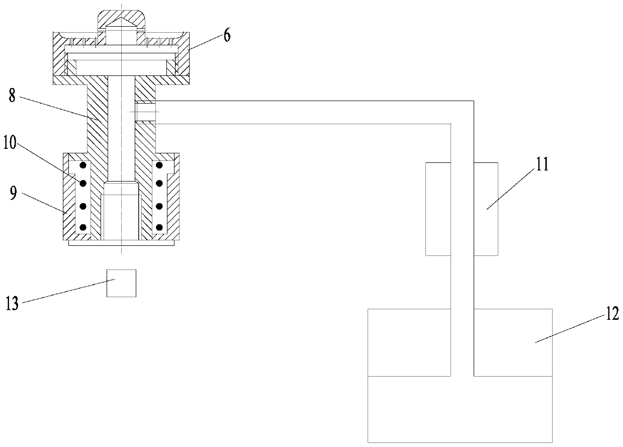
[0073] Install the first oil nipple 6 of the buffer block oiling tool on the protruding ring 83 of the oil nipple fixing seat 8, and tighten the first oil nipple 6.

[0074] (2) The buffer block is placed on the buffer block oiling tool, and the cylindrical end 31 of the buffer block is smeared with grease;

[0075] The specific process of step (2) is: place the buffer block in the first accommodation groove 67 of the first oil nozzle 6 with the cylindrical end 31 facing down, and insert the boss 62 into the central hole 37 of the buffer block , the buffer block is in a vertical state; then press the buffer block downwards, the buffer block pushes down the nozzle fixing seat 8 and the ...

Embodiment 2

[0080] This embodiment provides a buffer block oiling method for such as figure 1 with figure 2 The cylindrical end 31 and the truncated conical end 32 of the shown buffer block are oiled, and the oiling method includes the following steps:

[0081] (1) Provide buffer block oiling tooling;

[0082] Install the second oil nipple 7 of the buffer block oiling tool on the protruding ring 83 of the oil nipple fixing seat 8, and tighten the second oil nipple 7.

[0083] (2) The buffer block is placed on the buffer block oiling tooling, and the frustum-shaped end 32 of the buffer block is smeared with grease;

[0084] The specific process of step (2) is: place the buffer block in the second accommodation groove 74 of the second oil nozzle 7 with the truncated conical end 32 facing down, and the buffer block is in a vertical state; then press the buffer block downwards. block, the buffer block pushes down the oil nozzle fixing seat 8 and the second oil nozzle 7 on it, when the oil...


PUM


Abstract

The invention discloses an oil smearing tool for a buffer block. The oil smearing tool comprises an oil nozzle fixing seat, a first oil nozzle and a second oil nozzle. A cavity containing oil is formed in the oil nozzle fixing seat. The first oil nozzle is detachably connected with the oil nozzle fixing seat and used for spitting out the oil. The second oil nozzle is detachably connected with the oil nozzle fixing seat and used for spitting out the oil. According to the oil smearing tool for the buffer block, the oil is evenly smeared onto the two ends of the buffer block, and the oil smearing effect is good. In addition, the amount of the smeared oil is easy to control, so that waste is avoided, and the smearing efficiency is improved.

Description

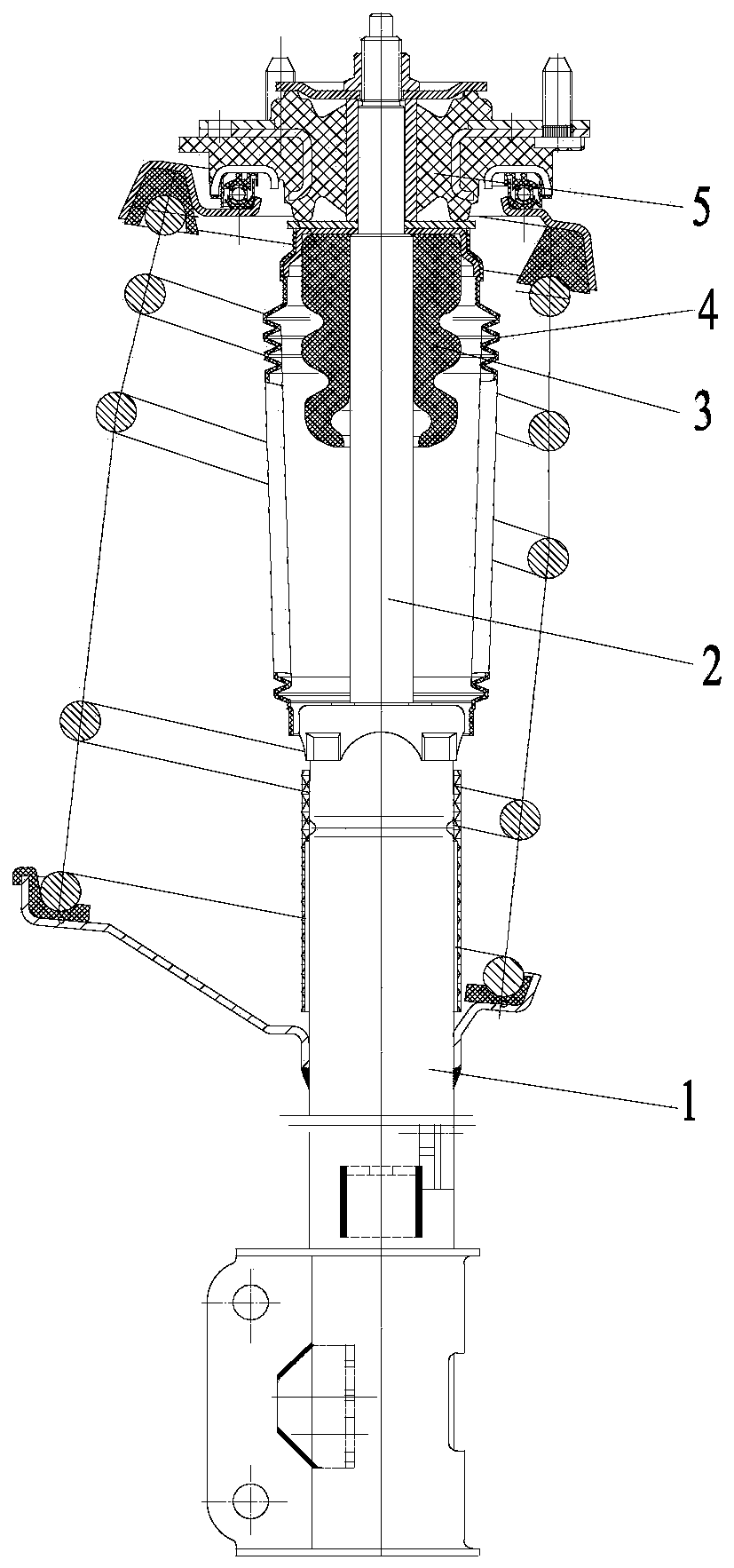
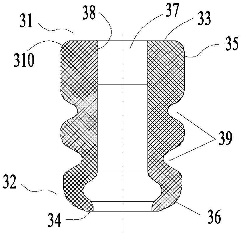
technical field [0001] The invention belongs to the technical field of tooling fixtures, in particular, the invention relates to a buffer block oiling tooling. Background technique [0002] Such as figure 1 with figure 2 As shown, the shock absorber used on the automobile includes a cylinder 1, a piston rod 2, a buffer block 3, a dust cover 4 and an upper support assembly 5, and the upper support assembly 5 is arranged on the upper end of the piston rod 2, and the buffer block 3 is sleeved on the piston rod 2 and located between the upper support assembly 5 and the cylinder 1, and the buffer block 3 is located inside the dust cover 4. The buffer block plays the role of buffering and limiting, and can be compressed and deformed. The buffer block is a cylindrical structure with multiple ring grooves 39 on the outer surface, and its inner center has a central hole 37 penetrating in the axial direction. The end contacting the support assembly is cylindrical, and the end face...

Claims


Application Information

Patent Timeline
IPC IPC(8): B05B13/02B05B12/00
CPCB05B13/02B05B13/0278B05B15/00
Inventor 舒晓雪赵以伟钟伟兴狄大庆杨明水章爱红
Owner 芜湖天佑汽车技术有限公司
Learn More