Suction pump

A technology for suction pumps and suction pipes, applied in the direction of pumps, pump control, pump devices, etc., can solve problems such as human or environmental hazards, unusable, dangerous, etc.

Inactive Publication Date: 2016-01-20
陈一海
View PDF5 Cites 1 Cited by
  • Summary
  • Abstract
  • Description
  • Claims
  • Application Information

AI Technical Summary

Problems solved by technology

[0002] Traditional suction pumps are equipped with motors, which are more dangerous or unusable when used in some areas that are sensitive to electricity
Moreover, it is difficult for traditional suction pumps to suck the liquid clean. If the toxic liquid cannot be sucked clean, it will cause harm to people or the environment.

Method used


Image

  • Suction pump
  • Suction pump

Examples


Embodiment Construction

[0013] The present invention will be described in further detail below in conjunction with the accompanying drawings.

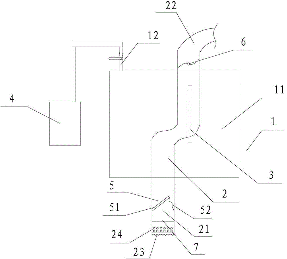
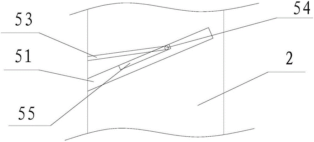
[0014] Such as figure 1 As shown, a suction pump includes a pump body 1 with a cavity 11 inside, a suction pipeline 2, an inner tube 3 and an air compressor 4, and the suction pipeline 2 passes through the cavity 11 in the pump body 1. One end of the suction pipe 2 is a suction end 21 , and the other end is a suction end 22 . A one-way valve 5 is provided in the suction pipe 2 and near the suction end 21 . Wherein, the one-way valve 5 includes a valve plate 51, one side of the valve plate 51 is hinged to the pipe wall of the suction pipe 2, and the other side is connected to the pipe wall of the suction pipe 2 by a spring 52 or a rope, and the spring 52 is used to limit The opening of the valve plate 51.

[0015] An impeller 6 is installed in the suction end 22 through a bracket, and the impeller 6 can transport liquid from the suction end 21 to the suction...


PUM


Abstract

The invention discloses a suction pump which comprises a pump body with a cavity formed inside, a suction pipe, an inner pipe and an air compressor. The suction pipe penetrates the cavity in the pump body. One end of the suction pipe is the suction end, and the other end of the suction pipe is the extraction end. A one-way valve is arranged on the position, close to the suction end, in the suction pipe. An impeller is arranged in the suction end. The inner pipe is arranged in the suction pipe. One end of the inner pipe faces the extraction end. The other end of the inner pipe penetrates the pipe wall of the suction pipe so that the cavity can be communicated with the suction pipe through the inner pipe. The pump body is provided with a valve communicated with the cavity. The air compressor is connected with the valve. In this way, the impeller is driven by compressed air to drain out liquid in the pipe, no motor is needed, and the suction pump can be suitable for regions sensitive to electricity and capable of sucking poisonous and harmful liquid completely.

Description

technical field [0001] The invention relates to a suction pump, in particular to a suction pump capable of sucking up liquid. Background technique [0002] Traditional suction pumps are equipped with motors, and when used in some areas that are sensitive to electricity, it is dangerous or impossible to use. Moreover, it is more difficult for traditional suction pumps to suck the liquid clean. If the toxic liquid cannot be sucked clean, it will cause harm to people or the environment. Contents of the invention [0003] The object of the present invention is to provide a suction pump that solves one or more of the above-mentioned problems in the prior art. [0004] According to one aspect of the present invention, a suction pump is provided, comprising a pump body with a cavity inside, a suction pipe, an inner pipe and an air compressor, the suction pipe passes through the cavity in the pump body; one end of the suction pipe The suction end is the suction end, and the othe...

Claims


Application Information

Patent Timeline
Patent Type & Authority Applications(China)
IPC IPC(8): F04D13/04F04D15/00F04D29/70
Inventor 陈一海
Owner 陈一海
Why Eureka
Try Eureka