Power line spiral adjustment plate
A technology for power lines and adjustment plates, applied in overhead lines/cable equipment, adjusting/maintaining mechanical tension, etc., can solve the problems of low labor intensity, achieve convenient adjustment and observation, avoid untimely adjustment, and facilitate live adjustment
- Summary
- Abstract
- Description
- Claims
- Application Information
AI Technical Summary
Problems solved by technology
Method used
Image
Examples
Embodiment 1
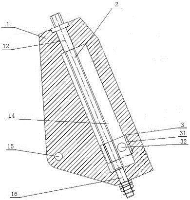
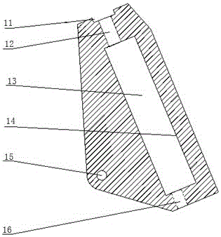
[0032] Such as Figure 1-Figure 5 As shown, the power circuit spiral adjustment plate includes the adjustment plate body 1, the screw body 2 and the slider body
[0033] 3. The adjusting plate body 1 includes a pillow block 11, a first bushing 12, a chute 13, a guide rail 14, an adjusting plate connecting hole 15 and a second bushing 16, and the adjusting plate connecting hole 15 is set on the adjusting plate body 1, the middle part of the adjusting plate body 1 has a through hole with narrow ends and a wide middle, the pillow block 11 is arranged on the top of the through hole, and the first bushing 12 is arranged on the upper part of the through hole. The second bushing 16 is arranged at the bottom of the through hole, the chute 13 is arranged at the middle of the through hole, and the guide rail 14 is arranged at one side of the chute 13;
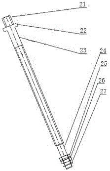
[0034] The screw body 2 is arranged in the middle through hole of the adjusting plate body 1, and the screw body 2 includes a hexagona...
Embodiment 2
[0043] Such as Figure 1-Figure 5 As shown, the power circuit spiral adjustment plate includes the adjustment plate body 1, the screw body 2 and the slider body
[0044] 3. The adjusting plate body 1 includes a pillow block 11, a first bushing 12, a chute 13, a guide rail 14, an adjusting plate connecting hole 15 and a second bushing 16, and the adjusting plate connecting hole 15 is set on the adjusting plate body 1, the middle part of the adjusting plate body 1 has a through hole with narrow ends and a wide middle, the pillow block 11 is arranged on the top of the through hole, and the first bushing 12 is arranged on the upper part of the through hole. The second bushing 16 is arranged at the bottom of the through hole, the chute 13 is arranged at the middle of the through hole, and the guide rail 14 is arranged at one side of the chute 13;
[0045] The screw body 2 is arranged in the middle through hole of the adjusting plate body 1, and the screw body 2 includes a hexagona...
Embodiment 3
[0055] Such as Figure 1-Figure 5 As shown, the power circuit spiral adjustment plate includes the adjustment plate body 1, the screw body 2 and the slider body
[0056] 3. The adjusting plate body 1 includes a pillow block 11, a first bushing 12, a chute 13, a guide rail 14, an adjusting plate connecting hole 15 and a second bushing 16, and the adjusting plate connecting hole 15 is set on the adjusting plate body 1, the middle part of the adjusting plate body 1 has a through hole with narrow ends and a wide middle, the pillow block 11 is arranged on the top of the through hole, and the first bushing 12 is arranged on the upper part of the through hole. The second bushing 16 is arranged at the bottom of the through hole, the chute 13 is arranged at the middle of the through hole, and the guide rail 14 is arranged at one side of the chute 13;
[0057] The screw body 2 is arranged in the middle through hole of the adjusting plate body 1, and the screw body 2 includes a hexagona...
PUM
 Abstract
Description
Claims
Application Information
 - R&D
- Intellectual Property
- Life Sciences
- Materials
- Tech Scout
- Unparalleled Data Quality
- Higher Quality Content
- 60% Fewer Hallucinations
Browse by: Latest US Patents, China's latest patents, Technical Efficacy Thesaurus, Application Domain, Technology Topic, Popular Technical Reports.
© 2025 PatSnap. All rights reserved.Legal|Privacy policy|Modern Slavery Act Transparency Statement|Sitemap|About US| Contact US: help@patsnap.com


