Supercharge Your Innovation With Domain-Expert AI Agents!

Marking device under electronic control

A marking device, electronic manipulation technology, applied in workshop equipment, manufacturing tools, etc., can solve the problem of time-consuming and so on

Inactive Publication Date: 2016-01-27
南京海联净化设备有限公司
View PDF0 Cites 0 Cited by
  • Summary
  • Abstract
  • Description
  • Claims
  • Application Information

AI Technical Summary

Problems solved by technology

This structure avoids the existing defect that the operator needs to support the mechanical parts to be punched, and the operator must remove the punched mechanical parts when the punching is completed, which takes a lot of time

Method used


Image

  • Marking device under electronic control
  • Marking device under electronic control

Examples


Embodiment Construction

[0016] Below in conjunction with accompanying drawing, content of the invention will be further described:

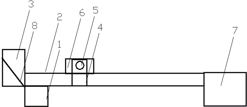
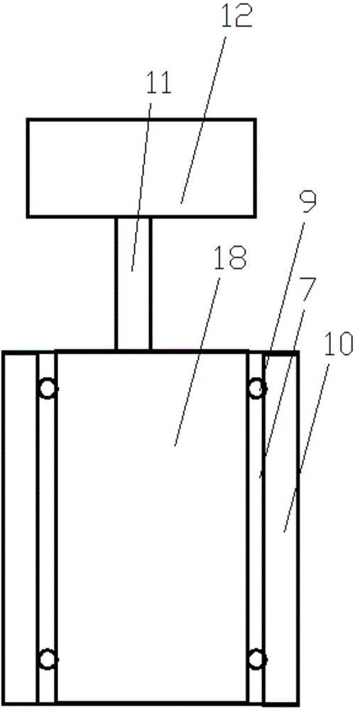
[0017] refer to figure 1 and figure 2 As shown, the engraving marking device under electronic control includes a conveyor belt 2 with a conveyor belt electric control system 1, the starting end of the conveyor belt 2 is connected to a mechanical component output cabinet 3, and one of the conveyor belt 2 is facing the set punching position. A pneumatic manipulator 4 with a photoelectric sensor 5 is arranged on the side, the sensing range of the photoelectric sensor 5 can cover the punching position, and a punching machine 6 is arranged on the other side of the conveyor belt 2 facing the set punching position , the end of the conveyor belt 2 is connected with the mechanical parts input cabinet 7 after punching. The mechanical parts output cabinet 3 is a cabinet structure, and the inside of the mechanical parts output cabinet 3 is an inclined plate 8, and a side panel 1...


PUM


Abstract

Provided is a marking device under electronic control. The marking device comprises a conveyor belt having an electronic control system of the conveyor belt. The initial end of the conveyor belt is connected with a mechanical part output cabinet. The side surface, right opposite to the set position for dotting punch, of the conveyor belt is provided with a pneumatic manipulator having a photoelectric sensor. The position for dotting punch is covered by the induction range of the photoelectric sensor. Another side surface, right opposite to the set position for dotting punch, of the conveyor belt is provided with a dotting punch machine. The tail end of the conveyor belt is connected with a dotting punch mechanical part input cabinet. The marking device under electronic control has following beneficial effects: due to the above-mentioned structure, the defect of time consumption in the prior art is avoided; and accordingly, operators do not need to support mechanical parts to be dotting punch and move mechanical parts subjected to dotting punch after dotting punch is finished performing.

Description

technical field [0001] The invention belongs to the technical field of marking devices, and in particular relates to a marking device under electronic manipulation. Background technique [0002] In the current field of machinery manufacturing, a large number of mechanical parts have the process of opening round grooves, but opening round grooves is not simple and difficult to open round grooves in place. The position of the groove is marked with the center of the circle, and this mark is usually marked by punching. [0003] Such engraving and marking devices now use microchips to operate mechanical punching equipment, but operators are required to support the mechanical parts to be punched. When the punching is completed, the operator must remove the punched mechanical parts, which is time-consuming. Very big. Contents of the invention [0004] The purpose of the present invention is to provide a marking device under electronic control, which includes a conveyor belt wit...

Claims


Application Information

Patent Timeline
IPC IPC(8): B25H7/04
Inventor 陈优国
Owner 南京海联净化设备有限公司
Features
  • R&D
  • Intellectual Property
  • Life Sciences
  • Materials
  • Tech Scout
  • Unparalleled Data Quality
  • Higher Quality Content
  • 60% Fewer Hallucinations
Learn More