Anti-icing starter solenoid switch with coil spring contacts

A helical spring and electromagnetic switch technology, applied in electromagnetic relays, electromagnetic relay details, circuits, etc., can solve the problems of starters not starting normally, heat loss, etc., and achieve the effect of safe and reliable use and simple structural design

Active Publication Date: 2017-04-26
JINZHOU HALLA ELECTRICAL EQUIP
View PDF9 Cites 0 Cited by
  • Summary
  • Abstract
  • Description
  • Claims
  • Application Information

AI Technical Summary

Problems solved by technology

When the electromagnetic coil is energized, the moving iron core moves down, thereby driving the moving contact rod and the moving contact piece to move down, so that the two ends of the moving contact piece are respectively connected to the two static contacts to conduct current, but there are the following problems: when the electromagnetic The temperature outside the switch drops, and the heat begins to lose from the switch casing. The two T-bolts used as static contacts are made of metal, so the heat loss is faster than the surrounding plastic insulation seat, and the temperature drops before other components. When the temperature is below 0°C, the water vapor inside the switch will condense into ice in the contact area on the surface of the static contact first, and the electromagnetic switch with frozen contacts will not be able to conduct the circuit, and the starter will not be able to start normally.
At present, there is no proven method to solve this problem

Method used


Image

  • Anti-icing starter solenoid switch with coil spring contacts

Examples


Embodiment Construction

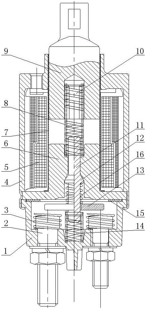
[0014] As shown in the figure, the anti-icing starter electromagnetic switch with helical spring contact includes a casing 4, an insulating seat 1 arranged at the bottom of the casing 4, two static contacts 2 arranged in the insulating seat 1, fixed on The ring-shaped support limit seat 6 above the insulating seat 1, the movable contact rod 11 pierced in the center of the ring-shaped support limit seat 6, the bottom end of the movable contact rod 11 and the angle between the movable contact rod 11 and the movable contact rod 11 are 90 degrees. The moving contact piece 13, the return spring 14 arranged between the lower end of the moving contact rod 11 and the bottom surface of the insulating seat 1, the sleeve 7 set on the outer periphery of the upper part of the annular support limit seat 6, and the sleeve 7 formed by the casing 4 The electromagnetic coil 5 in the annular space is arranged in the sleeve 7 and is supported by the supporting spring 8 on the moving iron core 9 on...


PUM


Abstract

The invention relates to an anti-icing starter electromagnetic switch with spiral spring contacts. The anti-icing starter electromagnetic switch comprises a shell, an insulation seat, two fixed contacts, an annular support limitation seat, a moving contact rod, a moving contact piece, a reset spring, a sleeve, an electromagnetic coil and a moving iron core, wherein the two fixed contacts are arranged in the insulation seat, the annular support limitation seat is fixedly arranged above the insulation seat, the moving contact rod is arranged at the center of the annular support limitation seat in a penetrating way, the moving contact piece is arranged at the lower end of the moving contact rod, the reset spring is arranged between the lower end of the moving contact rod and the bottom surface of the insulation seat, the sleeve sleeves the periphery of the upper part of the annular support limitation seat, the electromagnetic coil is arranged outside the sleeve, the moving iron core is arranged in the sleeve and supported at the top of the annular support limitation seat, the anti-icing starter electromagnetic switch is characterized in that the peripheries of the two fixed contacts in the insulation seat respectively envelops a spiral spring, the upper end of the spiral spring is a free end, the lower end of the spiral spring is welded with the lower parts of the fixed contacts, the top of the spiral spring is higher than the top surfaces of the fixed contacts in a free state and lower than the lower surface of the moving contact piece in a non-working state, and the spiral spring is made of an alloy with electrical resistivity greater than those of the fixed contacts. The anti-icing starter electromagnetic switch is simple in structure and is reliable to use.

Description

technical field [0001] The invention relates to a starter electromagnetic switch for vehicles, in particular to an anti-icing starter electromagnetic switch with a spiral spring contact. Background technique [0002] The traditional starter electromagnetic switch includes a casing, an insulating seat arranged at the bottom of the casing, two static contacts arranged in the insulating seat, an annular support limit seat fixed above the insulating seat, and a center of the annular support limit seat. The moving contact rod, the moving contact piece fixed at the lower end of the moving contact rod and forming an angle of 90 degrees with the moving contact rod, the return spring set between the lower end of the moving contact rod and the bottom surface of the insulating seat, set on the ring support The sleeve on the outer periphery of the upper part of the limit seat, the electromagnetic coil arranged in the annular space formed by the sleeve and the casing, the moving iron cor...

Claims


Application Information

Patent Timeline
Patent Type & Authority Patents(China)
IPC IPC(8): H01H50/12H01H50/54
CPCH01H50/12H01H50/54
Inventor 陈鹏李文奎
Owner JINZHOU HALLA ELECTRICAL EQUIP
Why Eureka
Try Eureka