Anti-icing starter solenoid switch with braided copper contacts

An electromagnetic switch, anti-icing technology, applied in electromagnetic relays, electromagnetic relay details, circuits, etc., can solve the problems of electromagnetic switches not conducting circuits, unable to reliably prevent icing, and starters failing to start normally. Solve the problem of unable to start normally, avoid icing, and have good anti-icing effect

Active Publication Date: 2018-04-06
JINZHOU HALLA ELECTRICAL EQUIP
View PDF7 Cites 0 Cited by
  • Summary
  • Abstract
  • Description
  • Claims
  • Application Information

AI Technical Summary

Problems solved by technology

When the electromagnetic coil is charged, the moving iron core moves down, thereby driving the moving contact rod and the moving contact piece to move down, so that the two ends of the moving contact piece are respectively connected with the two static contacts to conduct current, but there are the following problems: when the electromagnetic The temperature outside the switch drops, and the heat begins to lose from the switch casing. The material of the two T-bolts as the static contact is metal, so the heat loss is faster than the surrounding plastic static contact seat, and the temperature is earlier than other When the component drops below 0°C, the water vapor inside the switch will first condense into ice on the contact area of ​​the two static contact surfaces, and the electromagnetic switch with frozen contacts cannot conduct the circuit, and the starter cannot start normally
However, the two sets of contact mechanisms introduce new problems: complex structure, high cost, and large volume
However, this solution also has shortcomings: because the coil spring contact has an ablation every time the switch is turned on, the upper end of the spring is almost the same as the height of the static contact after being consumed by multiple ablation. Unreliable protection against icing at end of life

Method used


Image

  • Anti-icing starter solenoid switch with braided copper contacts
  • Anti-icing starter solenoid switch with braided copper contacts
  • Anti-icing starter solenoid switch with braided copper contacts

Examples


Embodiment 1

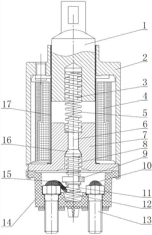
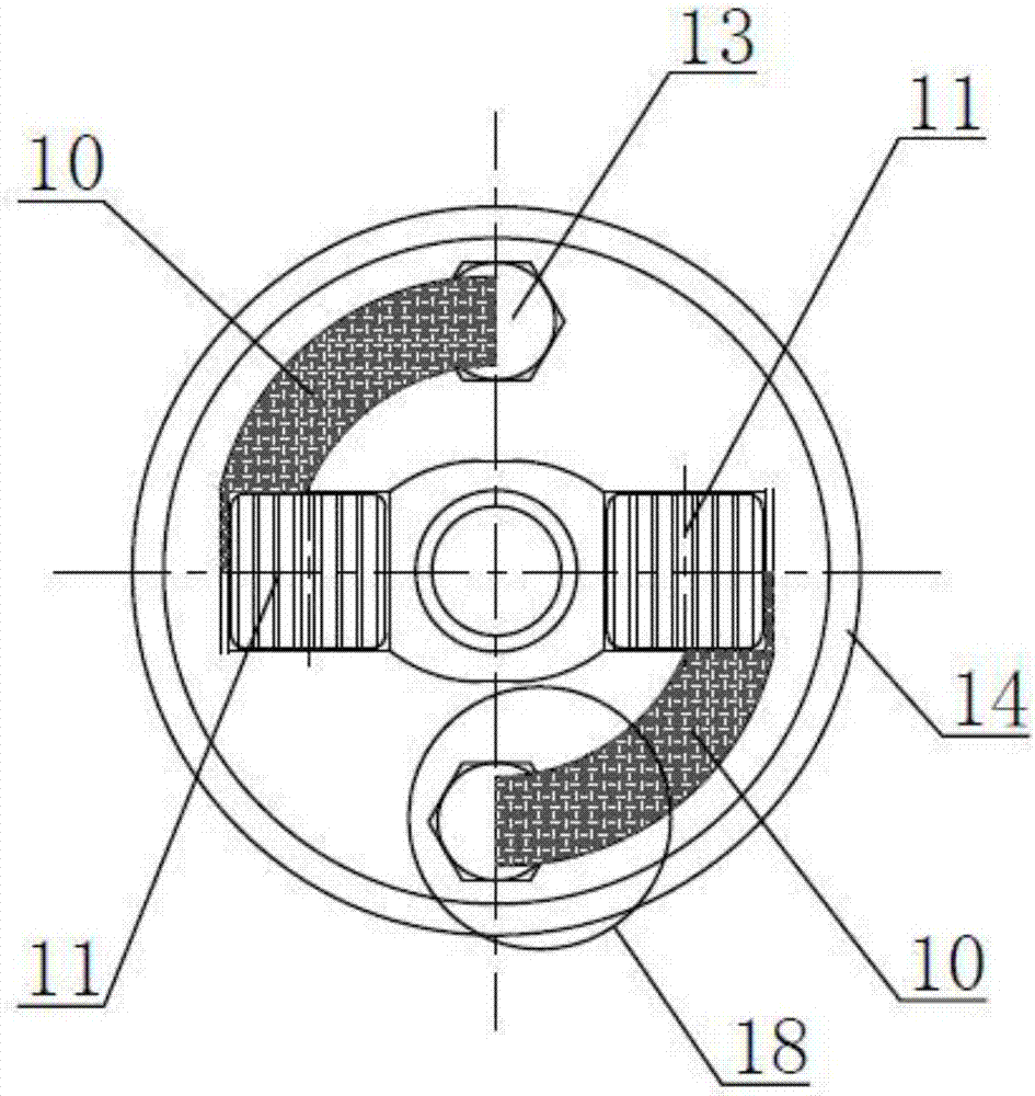
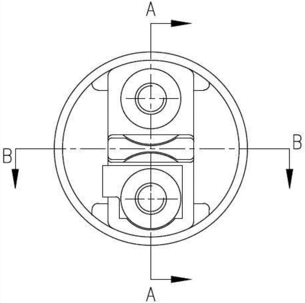
[0036] Such as Figure 1-Figure 5 As shown, the anti-icing starter electromagnetic switch with braided copper contacts includes a housing 2, a static contact seat 14 located at the bottom of the housing 2, two wiring terminals 13 located in the static contact seat 14, a fixed The ring-shaped support limit seat 7 above the static contact seat 14, the movable contact rod 6 set in the center of the ring-shaped support limit seat 7, the movable contact rod 6 arranged at the lower end of the movable contact rod 6 and perpendicular to the movable contact rod 6 Sheet 9, the return spring 12 set between the lower end of the moving contact rod 6 and the bottom surface of the static contact seat 14, the sleeve 17 set on the outer periphery of the upper part of the annular support limit seat 7, and the sleeve 17 formed by the shell 2 The electromagnetic coil 4 in the annular space, the moving iron core 1 that is located on the top of the annular support limit seat 7 and can slide along t...

Embodiment 2

[0040] Such as Figure 6 As shown, in the anti-icing starter electromagnetic switch with braided copper contacts, the terminal 13 is composed of a screw 1301 and a radiator 1302 arranged on the top of the screw 1301 . The radiator 1302 is composed of a bottom plate 1302a and a plurality of parallel vertical fins 1302b evenly distributed on the upper surface of the bottom plate 1302a, and the copper braid 10 is connected to the top of the vertical fins 1302b. When the external air temperature of the electromagnetic switch drops due to the weather, water vapor will condense on the radiator 1302 and the part of the copper braid 10 close to the radiator 1302 . Others are the same as embodiment 1.

Embodiment 3

[0042] Such as Figure 7 As shown, in the anti-icing starter electromagnetic switch with braided copper contacts, the terminal 13 is composed of a screw 1301 and a radiator 1302 arranged on the top of the screw 1301 . The radiator 1302 is composed of a bottom plate 1302a, a plurality of parallel vertical fins 1302b evenly distributed on the upper surface of the bottom plate 1302a, and a top plate 1302c parallel to the bottom plate 1302a arranged on the top of the vertical fins 1302b. 10 is connected to the top plate 1302c. When the external air temperature of the electromagnetic switch drops due to the weather, water vapor will condense on the radiator 1302 and the part of the copper braid 10 close to the radiator 1302 . Others are the same as embodiment 1.


PUM


Abstract

The invention relates to an anti-icing starter electromagnetic switch with a steel wire strand contact. The switch is characterized in that a through hole is formed in the middle of a movable contact piece, the lower end of a movable contact rod penetrates through the through hole of the movable contact piece and prevents the movable contact piece from being separated from the movable contact rod by means of torsion spring limiting, the movable contact rod between an annular limiting boss and the movable contact piece is sleeved with a pressure spring, two static contacts are additionally arranged on the bottom face in a static contact base, the static contacts and binding posts correspond one to one and are connected with steel wire strands, the two ends of the movable contact piece correspond to the upper surfaces of the two static contacts, and each binding post is a hexagonal bolt or composed of a screw and a radiator on the top of the screw. The icing problem of a starter switch contact is fundamentally solved, and the switch is simple in structure, small in size, reliable to use and wide in application range.

Description

technical field [0001] The invention relates to a starter electromagnetic switch for vehicles, in particular to an anti-icing starter electromagnetic switch with braided copper contacts. Background technique [0002] The traditional starter electromagnetic switch consists of a housing, a static contact seat located at the bottom of the housing, two static contacts located in the static contact seat, a ring support limit seat fixed above the static contact seat, and a ring support The moving contact rod in the center of the limit seat, the moving contact sheet fixed on the lower end of the moving contact rod and perpendicular to the moving contact rod, the return spring arranged between the lower end of the moving contact rod and the bottom surface of the static contact seat, is set on The sleeve on the outer periphery of the upper part of the annular support limit seat, the electromagnetic coil arranged in the annular space formed by the sleeve and the casing, the moving iro...

Claims


Application Information

Patent Timeline
Patent Type & Authority Patents(China)
IPC IPC(8): H01H51/06H01H50/54H01H50/12
CPCH01H50/12H01H50/54H01H51/065
Inventor 白昆陈鹏任琛
Owner JINZHOU HALLA ELECTRICAL EQUIP
Why Eureka
Try Eureka