Eureka AIR delivers breakthrough ideas for toughest innovation challenges, trusted by R&D personnel around the world.

Motor rotor and self-starting synchronous motor

A motor rotor and permanent magnet technology, applied in synchronous machines, magnetic circuit rotating parts, electromechanical devices, etc., can solve the problems of poor motor starting ability and lack of spiral structure, reduce braking torque and solve technical difficulties , reduce the effect of harmonics

Active Publication Date: 2018-12-21
GREE ELECTRIC APPLIANCES INC +1
View PDF5 Cites 0 Cited by
  • Summary
  • Abstract
  • Description
  • Claims
  • Application Information

AI Technical Summary

Problems solved by technology

Poor starting ability of the motor due to lack of helical structure in the rotor core and cast aluminum squirrel cage

Method used


Image

  • Motor rotor and self-starting synchronous motor
  • Motor rotor and self-starting synchronous motor
  • Motor rotor and self-starting synchronous motor

Examples


Embodiment 1

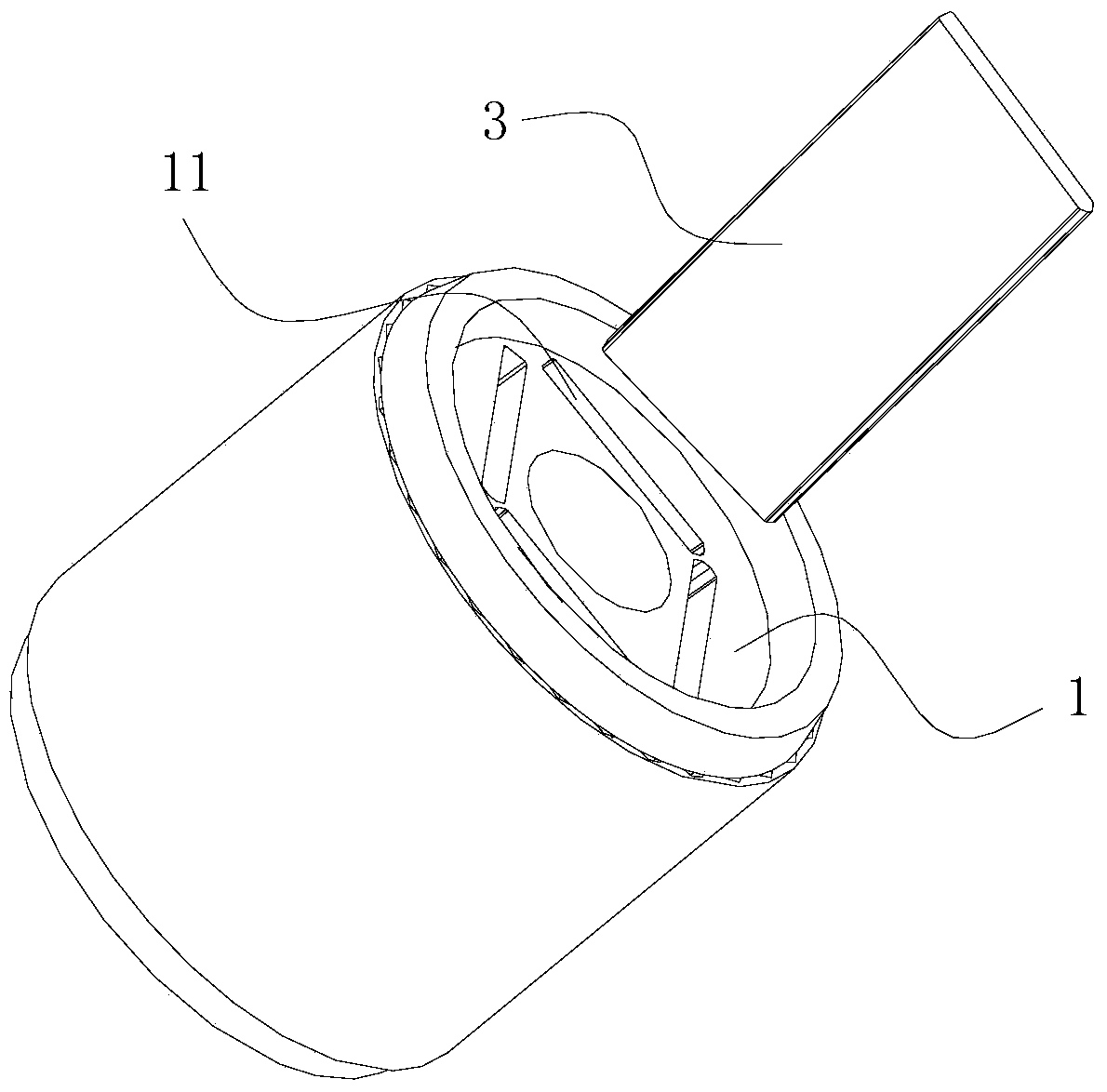
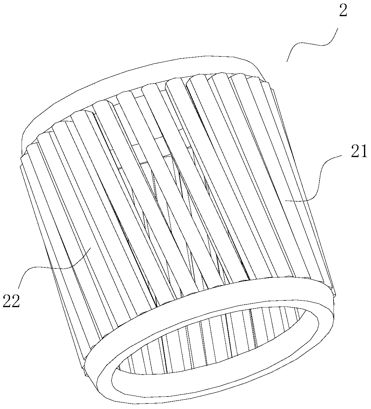
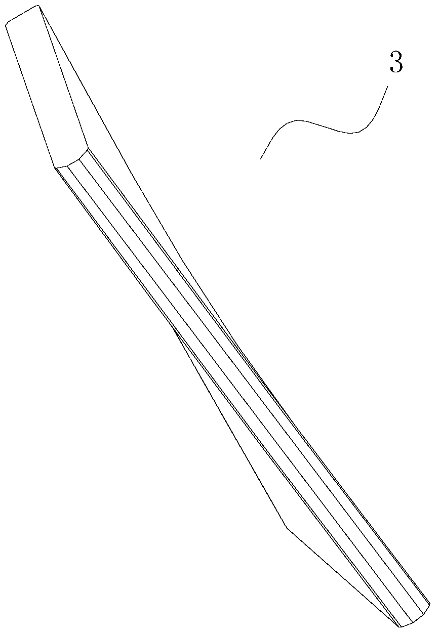
[0027] The preferred embodiment discloses a motor rotor. Such as Figure 1 to Figure 4 As shown, the motor rotor includes an iron core 1, a squirrel cage 2, and a permanent magnet 3. Among them, the permanent magnet 3 has a plate-shaped structure, and at least a part of the area on the permanent magnet 3 is bent toward the vertical direction of the plane to which the permanent magnet 3 belongs. The side wall column 21 of the squirrel cage 2 is inclined with respect to the bottom surface, and a chute 22 is formed between the side wall column 21; the inclination angle of the side wall column 21 matches the bending angle of the permanent magnet 3. The iron core 1 is provided with a slot 11 which is inclined with respect to the bottom surface; the inclination angle of the slot 11 is adapted to the bending angle of the permanent magnet 3.

[0028] After installation, the iron core 1, the squirrel cage 2 and the permanent magnet 3 are all spirally stretched from the bottom surface of...

Embodiment 2

[0031] The preferred embodiment discloses a self-starting synchronous motor including a stator, and the motor is provided with a rotor as described in the first preferred embodiment. The side wall columns of the squirrel cage are inclined with respect to the bottom surface, and a slanted slot is formed between the side wall columns, and the span of the slanted slot is a stator tooth width, which increases the starting ability of the motor and reduces the influence of harmonics.


PUM


Abstract

The invention discloses a motor rotor and a self-starting synchronous motor, belongs to the field of the motors and the accessories, and is designed for solving the problem that the existing structure is bad in starting capacity. The motor rotor comprises an iron core, a mouse cage and a permanent magnet, the permanent magnet is a platy structure, and at least partial region on the permanent magnet is bent towards a vertical direction of a plane to which the permanent magnet belongs. The self-starting synchronous motor comprises a stator, and the motor is provided with the above rotor. The motor rotor disclosed by the invention is capable of reducing harmonic wave when the motor is started, reducing the brake torque while starting, and improving the starting capacity of the motor. The self-starting synchronous motor disclosed by the invention solves the technical difficulty that the self-starting synchronous motor cannot be widely applied, the starting capacity is excellent, and the advantage of the motor can be efficiently exerted.

Description

Technical field [0001] The invention relates to the field of motors and their accessories, in particular to a motor rotor and a self-starting synchronous motor provided with the rotor. Background technique [0002] The rotor structure of the self-starting synchronous motor (also known as the asynchronous start synchronous motor) is mainly to insert permanent magnets in the cast aluminum rotor, which can have higher efficiency due to the permanent magnets of the rotor during operation. [0003] In order to realize this insertion structure, the existing permanent magnet has a regular block structure (or called a sheet structure or a plate structure), and the rotor core and cast aluminum squirrel cage matched with it are relative to the bottom surface. Vertical tensile structure. Due to the lack of spiral structure of the rotor core and cast aluminum squirrel cage, the starting ability of the motor is deteriorated. Summary of the invention [0004] An object of the present invention ...

Claims


Application Information

Patent Timeline
Patent Type & Authority Patents(China)
IPC IPC(8): H02K1/27H02K21/46
Inventor 刘贤义范少稳
Owner GREE ELECTRIC APPLIANCES INC
Why Eureka
Eureka Blog
Learn More