Method for controlling at least one lighting facility of a vehicle and controlling method

A technology for lighting equipment and vehicles, which is applied in the field of computer programs, can solve problems such as hazards to traffic participants, and achieve the effects of avoiding dazzling hazards, small additional costs, and improving safety

Inactive Publication Date: 2016-01-27
ROBERT BOSCH GMBH
View PDF4 Cites 9 Cited by
  • Summary
  • Abstract
  • Description
  • Claims
  • Application Information

AI Technical Summary

Problems solved by technology

In practice, this is also often forgotten, which likewise creates a hazard for other road users

Method used


Image

  • Method for controlling at least one lighting facility of a vehicle and controlling method
  • Method for controlling at least one lighting facility of a vehicle and controlling method
  • Method for controlling at least one lighting facility of a vehicle and controlling method

Examples


Embodiment Construction

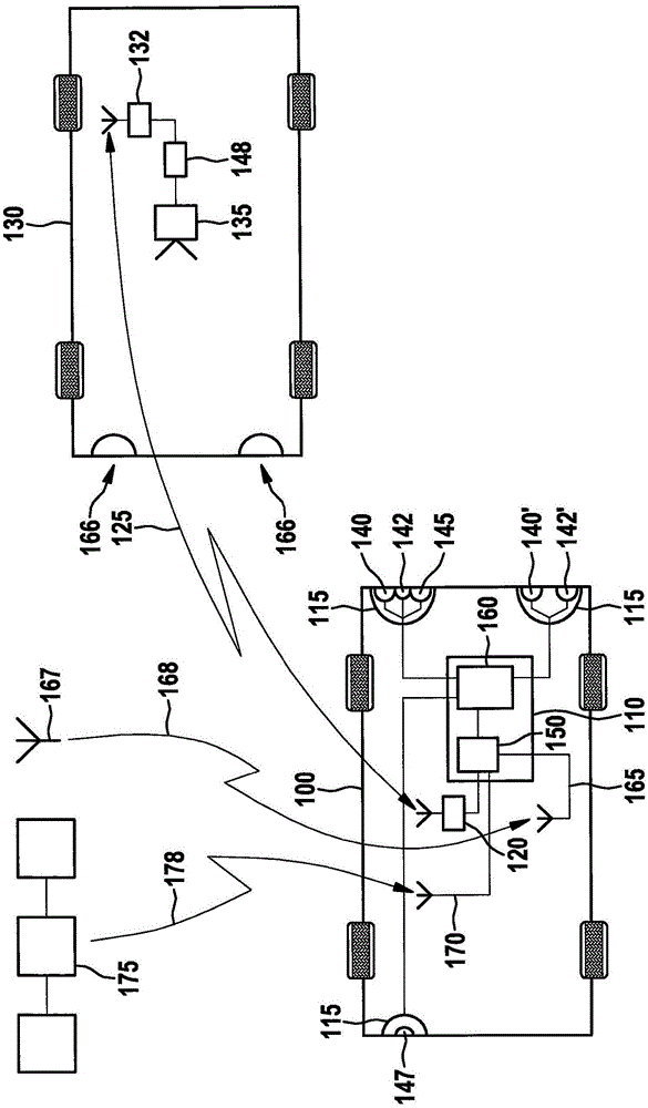
[0030] figure 1 A block diagram of a vehicle 100 with a device 110 for controlling at least one lighting device 115 is shown. The device 110 is connected to a receiving unit 120 which is designed to receive a communication signal 125 from a transmitting unit 132 (which is arranged, for example, in a further vehicle 130 ) (which can also be designed as a receiving unit for another purpose described below), The receiving unit is thus arranged outside the vehicle 100 or in a traffic infrastructure unit described in more detail later. In this case, communication signal 125 may contain information read by camera 135 and representing, for example, an operating state of lighting system 115 of vehicle 100 . For example, it is conceivable that the high-beam headlight 140 or another high-beam headlight 140 ′ of the lighting device 115 is detected by means of the camera 135 to be activated (ie switched on), so that when another vehicle 130 approaches (ie, the direction of travel of the ...


PUM


Abstract

The present invention provides a method (200) for controlling at least one lighting facility (115) of a vehicle (100). The method (200) includes one step (200) of reading a communication signal (125) transmitted by transmitting units (132,410) arranged on the outside of the vehicle. Additionally, the method (200) includes one step (220) of changing the operation state of the lighting facility by responding to the read communication signal (125).

Description

technical field [0001] The invention relates to a method for controlling at least one lighting device of a vehicle, a corresponding control device and a corresponding computer program. Background technique [0002] Car-to-car communication or car-to-car communication (Car2Car or C2C) is understood to mean the exchange of information and data between motor vehicles. The purpose of the data exchange is to inform the driver of critical and dangerous situations in advance. The vehicles involved collect data such as ABS intervention, steering angle, position, direction and speed and transmit these data via radio (WLAN, UMTS . . . ) to other road users. Here, the "sight distance" of the driver should be extended by means of electronic means. Vehicle-to-infrastructure communication or vehicle-to-infrastructure communication (C2I) is understood to be the exchange of data between a vehicle and the surrounding infrastructure or infrastructure devices (for example optical signaling s...

Claims


Application Information

Patent Timeline
Patent Type & Authority Applications(China)
IPC IPC(8): H05B37/02
CPCB60Q1/1423B60Q2300/47B60Q2900/30
Inventor M·R·埃韦特
Owner ROBERT BOSCH GMBH
Why Eureka
Try Eureka