Latch system for door
A latching and locking groove technology, applied in the field of latching systems, can solve the problems of complicated assembly operations, increase manufacturing costs, etc., and achieve the effect of reducing the number of parts and avoiding being bent
- Summary
- Abstract
- Description
- Claims
- Application Information
AI Technical Summary
Problems solved by technology
Method used
Image

Examples
no. 1 approach
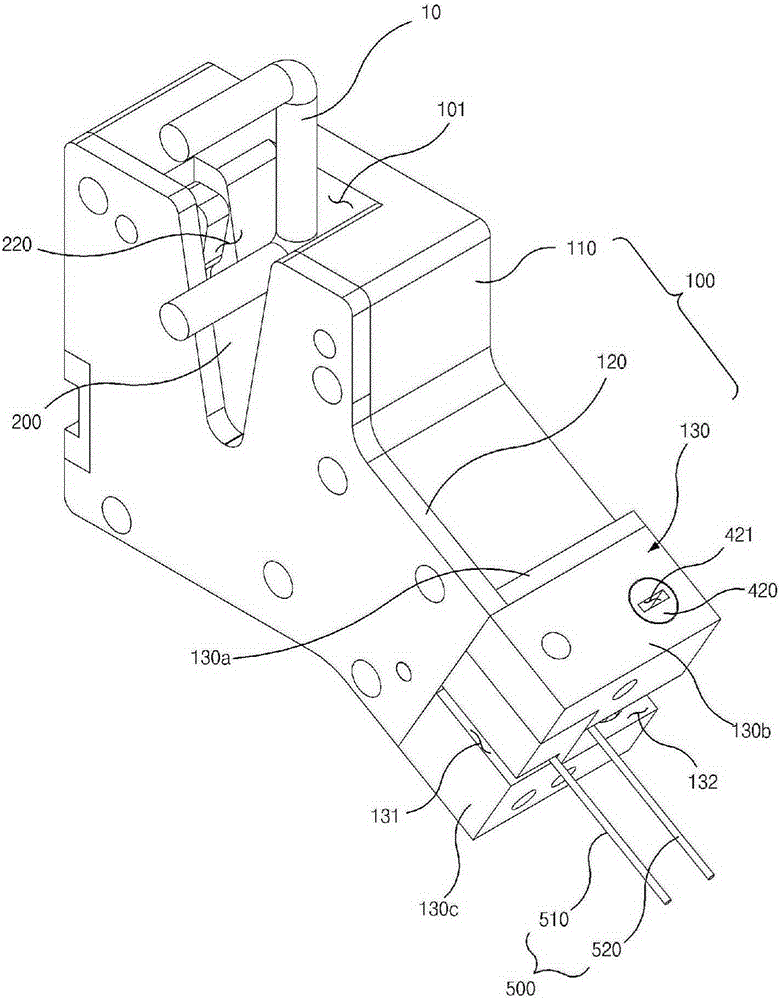
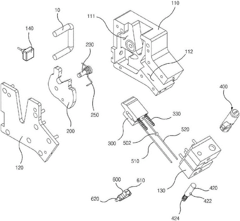
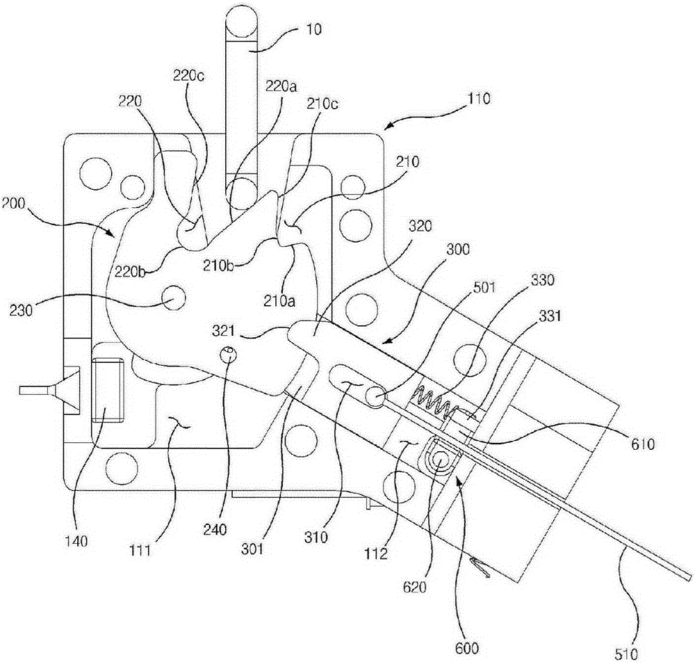
[0059] like figure 1 As shown in FIG. 8 , the latch system for a door according to the first embodiment of the present invention includes a housing 100 , a latch 200 and a locking member, the latch 200 is rotatably installed at the housing 100 , and the locking member is installed At the housing 100 the latch 200 is thus locked. The locking member includes a sliding member 300 slidably installed at the housing 100 , the latch 200 is installed to be rotatable, and the sliding member 300 is installed to be linearly movable.
[0060] The casing 100 includes a first casing 110, a second casing 120 and a third casing 130, the second casing 120 is arranged in front of the first casing 110, and the third casing 130 is arranged on the first casing 110. and the side of the second casing 120 .
[0061] A link insertion groove 101 is formed at a front upper portion of the housing 100 , and a link 10 connected to a door (not shown) is inserted into the link insertion groove 101 .
[00...
no. 2 approach
[0148] like Figure 9 to Figure 1 2, the door latch system according to the second embodiment of the present invention further includes a latch driving part 240', and the latch driving part 240' rotates the latch 200" to the locked position.
[0149] Illustration and description of elements of this embodiment that are similar or identical to elements of the first embodiment will be omitted.
[0150] A motor or the like may be used as the latch driving part 240, and the latch driving part 240 is mounted on the rear side of the first housing 110" through a driving part bracket 243.
[0151] The stopper part 242 is formed at the shaft 241 of the latch driving part 240 and protrudes forward.
[0152] The stopper part 242 is disposed radially spaced apart from the shaft 241 .
[0153] A reduction gear (not shown) is installed at the shaft 241 of the latch driving part 240 .
[0154] The stop member guide groove 116 is formed on the left side of the first housing 110 ″ and commun...
no. 3 approach
[0189] like Figure 13 to Figure 1 7, in the latch system for a door according to the third embodiment of the present invention, the locking member includes a rotating member 340 rotatably installed on the housing 100' and the sliding member 300'.
[0190] Illustration and description of elements of this embodiment that are similar or identical to elements of the first embodiment will be omitted.
[0191] A groove-type spring moving part 113' in which the first return spring 250 moves is formed on the front surface of the first housing 110' and communicated with the latch seating groove 111'. The groove type spring moving part 113' is disposed in the latch seating groove 111'.
[0192] like Figure 15 As shown, the rotating member seating groove 115 is formed on the front surface of the first housing 110' and is disposed at the upper right portion of the latch seating groove 111'. The rotating member seating groove 115 communicates with the latch seating groove 111'.
[01...
PUM
 Abstract
Description
Claims
Application Information
 - R&D
- Intellectual Property
- Life Sciences
- Materials
- Tech Scout
- Unparalleled Data Quality
- Higher Quality Content
- 60% Fewer Hallucinations
Browse by: Latest US Patents, China's latest patents, Technical Efficacy Thesaurus, Application Domain, Technology Topic, Popular Technical Reports.
© 2025 PatSnap. All rights reserved.Legal|Privacy policy|Modern Slavery Act Transparency Statement|Sitemap|About US| Contact US: help@patsnap.com