Connection structure of refrigerant tube

A refrigerant pipe and connection structure technology, which is applied in the direction of sealing surface connection, pipe/pipe joint/pipe fitting, heating method, etc., can solve the problems of impossibility of airtightness, refrigerant gas leakage, and difficulty in ensuring airtightness, etc. , to achieve the effect of improving the efficiency of cooling/heating and preventing air leakage

Inactive Publication Date: 2016-02-03
吴炯东
View PDF7 Cites 9 Cited by
  • Summary
  • Abstract
  • Description
  • Claims
  • Application Information

AI Technical Summary

Problems solved by technology

[0012] In the refrigerant pipe connection structure of Registered Patent No. 10-1195425 constituted as described above, stainless steel is used for the outer sleeve 30 and inner sleeve 50, aluminum is used for the refrigerant pipe 20, and copper is used for the valve 10 and the nut 40. Since the above-mentioned parts with different materials have different thermal expansion coefficients, as the air conditioner continues to repeatedly operate and stop, it is difficult to ensure airtightness due to the different shrinkage and expansion rates of the above-mentioned parts. Although it is a combination of metals It is easier to achieve a strong bond but impossible to achieve complete airtightness, resulting in leakage of refrigerant gas and a reduction in the cooling / heating efficiency of the air conditioner
[0013] Moreover, when the above-mentioned valve 10 and nut 40 are fastened firmly, the expanded pipe portion 21 of the refrigerant pipe 20 is image 3 As shown, problems such as cracks or cracks occur, making it difficult to ensure airtightness, resulting in leakage of refrigerant gas and a decrease in the cooling / heating efficiency of the air conditioner

Method used


Image

  • Connection structure of refrigerant tube
  • Connection structure of refrigerant tube
  • Connection structure of refrigerant tube

Examples


Embodiment Construction

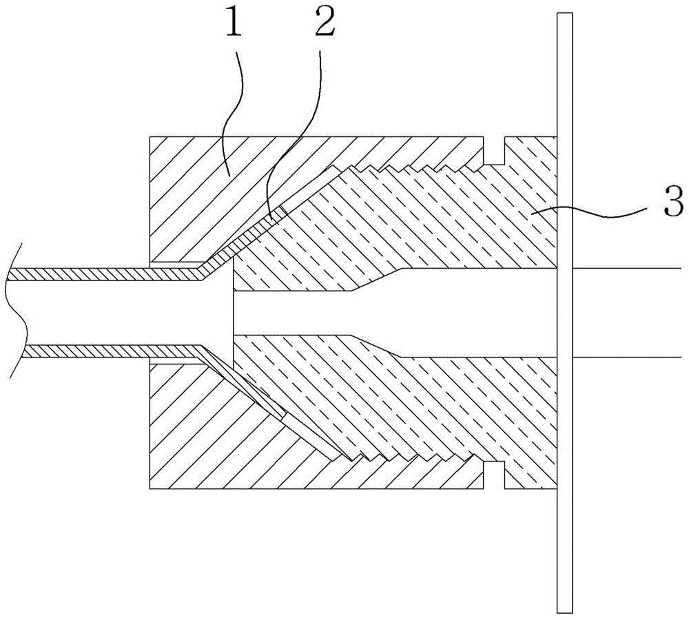
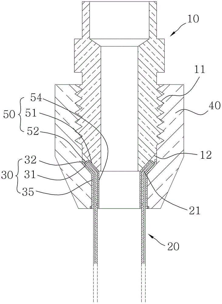
[0049] Combine below Figure 4 to Figure 6 Embodiments of the refrigerant pipe connection structure of the present invention will be described.

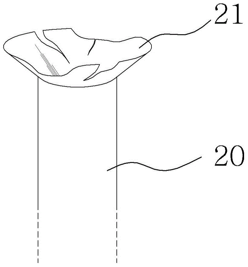
[0050] In the refrigerant pipe connection structure of the present invention, the nut 170 is inserted into the refrigerant pipe 140 and then the bolt 110 and the nut are combined in order to closely combine the expanded portion 141 of the refrigerant pipe 140 with the tapered portion 113 of the valve 110 to maintain airtightness. 170 and fasten the thread, the male thread 112 of the valve 110 and the female thread 172 of the nut 170 can be screwed together so that the expansion part 141 of the refrigerant tube 140 is firmly fastened to the tapered part of the valve 110 113.

[0051] At this time, the material of the refrigerant pipe 140 on which the above-mentioned expanded portion 141 is formed is aluminum and the valve 110 is one of copper, iron, or stainless steel. Therefore, if the nut 170 is tightened excessively, the expanded ...


PUM


Abstract

The present invention relates to a connecting structure of a refrigerant pipe, capable of connecting each end part of a refrigerant pipe for inducing a refrigerant gas flow between indoor and outdoor units for making up a cooling device, a heating device, or a cooling/heating device in order to maintain the airtightness. Moreover, the connecting structure of a refrigerant pipe comprises: a valve installed in the corresponding place of indoor and outdoor units of an air conditioner; a refrigerant pipe including a pipe expansion part in the form of a trumpet in the front; an outer sleeve including an outer pipe expansion part inserted into the refrigerant pipe and combined with the outside of the pipe expansion part; an inner sleeve including an inner pipe expansion part inserted into and combined with the pipe expansion part; a nut screwed with the valve by being inserted into the refrigerant pipe to accommodate the outer sleeve inside; a first sealing member in a form to correspond to the form of the inner sleeve having contraction and expansion forces while ensuring airtightness between the inner sleeve and the lower part of the valve; and a second sealing member having contraction and expansion forces while ensuring airtightness between the outer sleeve and the inside of the nut.

Description

technical field [0001] The present invention relates to a connection structure of refrigerant pipes, which can maintain the airtight connection of the end parts of the refrigerant pipes, and the refrigerant pipes are guided to form cooling or heating devices and cooling / heating devices (hereinafter referred to as "air conditioners"). Refrigerant gas flows between the indoor and outdoor units of the unit”). Background technique [0002] Air conditioners are usually divided into indoor and outdoor units, and between the indoor and outdoor units, refrigerant pipes are connected to each other to allow refrigerant gas to flow. Maintain an airtight installation. [0003] As mentioned above, most of the existing refrigerant pipes installed to maintain airtightness use copper (Cu) pipes, and the prior art of using the copper pipes to connect the end parts of the refrigerant pipes to each other can be cited from Japanese Publication of Utility Models. Publication No. 50-045946 as a...

Claims


Application Information

Patent Timeline
Patent Type & Authority Applications(China)
IPC IPC(8): F16L19/025F16L19/03F24F1/32
CPCF16L19/04F24F1/32
Inventor 吴炯东
Owner 吴炯东
Why Eureka
Try Eureka