Eureka AIR delivers breakthrough ideas for toughest innovation challenges, trusted by R&D personnel around the world.

Sample stage

A technology of sample stage and sample tray, which is applied in the direction of measuring devices, instruments, measuring electronics, etc., and can solve the problems of different sample sizes and sample stages that cannot meet the requirements

Active Publication Date: 2016-02-03
INFINITE MATERIALS TECH
View PDF6 Cites 1 Cited by
  • Summary
  • Abstract
  • Description
  • Claims
  • Application Information

AI Technical Summary

Problems solved by technology

Since the distance between the sample and the needle tip must be controlled at a fixed micro size, guaranteed to be in the order of um, and the samples are of different sizes, the existing sample stages cannot meet the requirements

Method used


Image

  • Sample stage
  • Sample stage
  • Sample stage

Examples


Embodiment Construction

[0029] The present invention will be further described below in conjunction with the accompanying drawings and specific embodiments, but not as a limitation of the present invention.

[0030] At present, when designing the measurement of electromagnetic parameters in the microwave band of materials, in order to obtain accurate measurement results, it is necessary to control the distance between the needle tip and the sample to be constant, and the size of the sample must be suitable for the size of a dedicated sample stage, which is used to place samples of different sizes. There must also be certain restrictions.

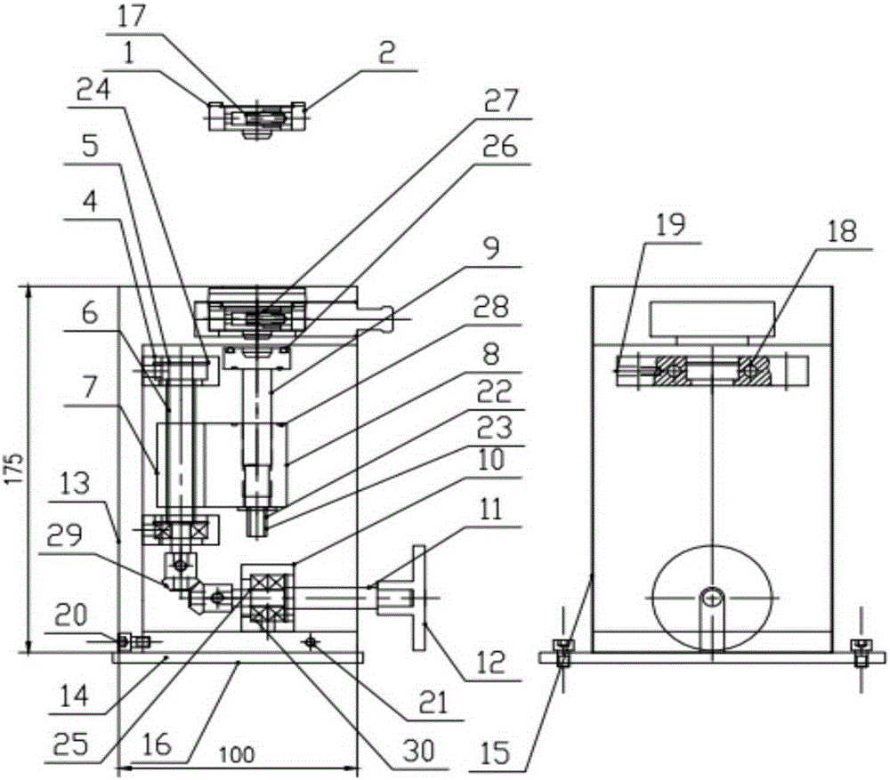
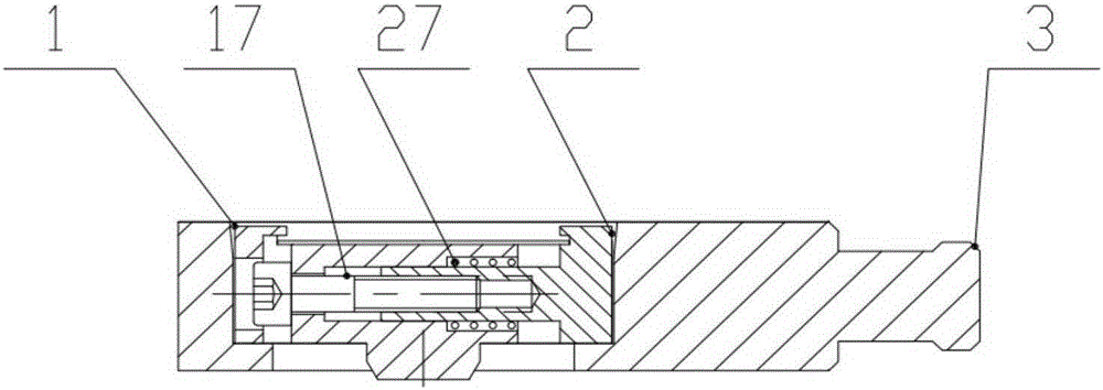
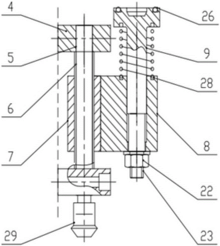
[0031] Such as figure 1 -As shown in Figure 5, 1. Sample clamp (304); 2. Sample clamp small block (304); 3. Sample tray (6061-T6); 4. Lifting seat (6061-T6); 5. Guide rail (304) ;6. Lifting screw (304); 7. Screw pair (H62); 8. Connector (H62); 9. Ejector (304); 10. Bearing seat (6061-T6); 11. Transmission shaft ( 304); 12. Turn the hand wheel (304); 13. Mounting ...


PUM


Abstract

The invention relates to the material microwave wave band electromagnetic parameter measurement field, especially a sample stage. The sample stage is composed of a sample stage assembly, an elevating assembly, a transmission assembly and a housing assembly; the elevating assembly and the transmission assembly are in precise connection, and can realize minimal distance transmission, thereby accurately controlling the displacement distance of the control stage assembly, furthermore more easily changing an observation distance in observing samples, and keeping observing samples at fixed minimal distances. In addition, the sample stage can telescope freely, thereby meeting observation requirements for samples of different dimensions, and is convenient and flexible.

Description

technical field [0001] The invention relates to the field of electromagnetic parameter measurement in the microwave band of materials, in particular to a sample stage. Background technique [0002] When designing the measurement of electromagnetic parameters in the microwave band of materials, there are two key parameters that will affect the final test results, one is the electromagnetic properties of the material (the data that needs to be measured in the end), and the other is the distance between the sample and the needle tip. In order to measure the results accurately, the distance between the needle tip and the sample must be controlled to be constant. Since the distance between the sample and the needle tip must be controlled in a fixed tiny size, guaranteed to be in the order of um, and the samples are of different sizes, none of the existing sample stages can meet the requirements. Contents of the invention [0003] In view of the above-mentioned problems, the pr...

Claims


Application Information

Patent Timeline
Patent Type & Authority Applications(China)
IPC IPC(8): G01R1/02
Inventor 向勇蒋常龙曹德王维项晓东
Owner INFINITE MATERIALS TECH
Why Eureka
Eureka Blog
Learn More