A high-precision multi-fin hobbing cutting machine

A high-precision cutting machine technology, applied in metal processing and other directions, can solve the problems of increased overall equipment height, large energy loss, and equipment confusion, and achieve the effects of lower overall height, less energy loss, and convenient transportation

Active Publication Date: 2016-01-20
NINGBO RONGZHI AUTOMATION TECH
View PDF10 Cites 0 Cited by
  • Summary
  • Abstract
  • Description
  • Claims
  • Application Information

AI Technical Summary

Problems solved by technology

The axial direction of the spline shaft and the axial direction of the transmission shaft are perpendicular to each other, and the energy loss through the bevel gear transmission is large
[0007] In addition, the servo motor in the fin propulsion mechanism and the entire cutting mechanism are arranged above the frame, which causes the equipment above the frame to be confused, and causes the overall height of the entire equipment to increase greatly. The equipment is bulky and inconvenient to transport, assemble and place, and maintenance is also difficult Inconvenient, and the driving source of the entire cutting mechanism is both a cylinder and a servo motor. The control part requires both mechanical control and electrical control. The overall structure is complicated and the cost is high.

Method used


Image

  • A high-precision multi-fin hobbing cutting machine
  • A high-precision multi-fin hobbing cutting machine
  • A high-precision multi-fin hobbing cutting machine

Examples


Embodiment Construction

[0027] The present invention will be further described in detail below in conjunction with the accompanying drawings and embodiments.

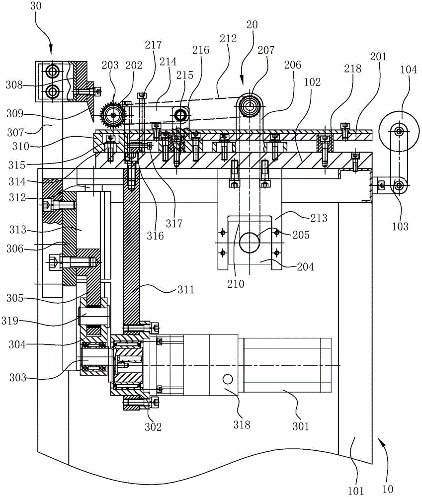
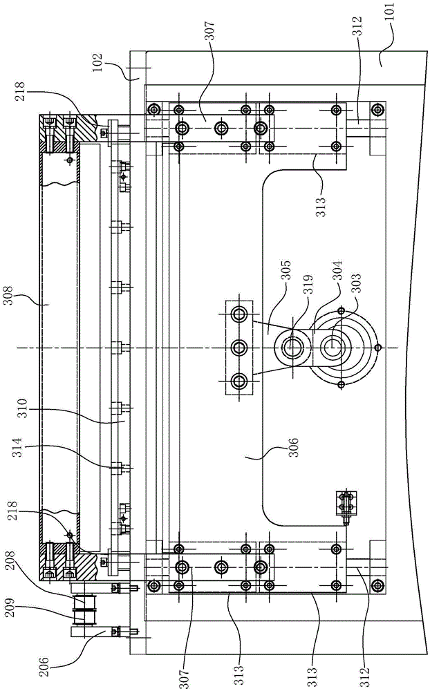
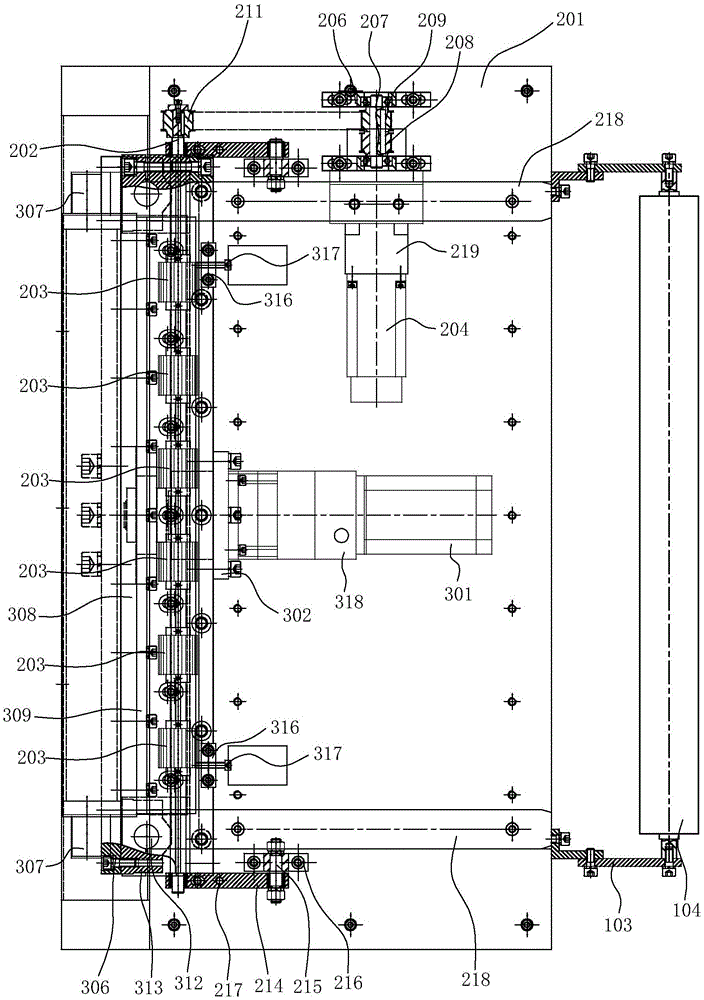
[0028] Such as Figure 1~4 Shown is a preferred embodiment of the present invention.

[0029] A high-precision multi-fin hobbing cutting machine, including a frame part 10, a fin propulsion mechanism 20 and a fin cutting part 30 arranged on the frame part, the fin propulsion mechanism 20 is used to push the fins 4 Move forward to the fin cutting section 30 for cutting.

[0030] The frame part 10 includes a bracket 101 and an installation platform 102 located on the upper part of the bracket. The rear side of the support 101 is fixed with a roller installation frame 103, and a material passing roller 104 is installed on the roller installation frame 103.

[0031] The fin propulsion mechanism 20 includes a support plate 201 fixed on the installation platform 102 for supporting the fin 4, a roller gear shaft 202 that can rotate around its own ...


PUM


Abstract

The invention relates to a high-precision hobbing cutting machine for a plurality of fins. The high-precision hobbing cutting machine for the fins comprises a rack portion, a fin feeding mechanism and a fin cutting-off portion. The high-precision hobbing cutting machine for the fins is characterized in that the fin feeding mechanism comprises a supporting plate, wherein the supporting plate is fixed to an installation platform, and is used for supporting the fins, a hobbing gear shaft which can rotate around the axis of the hobbing gear shaft is arranged above the supporting plate, the axial direction of the hobbing gear shaft is perpendicular to the movement direction of the fins, a gap exists between the hobbing gear shaft and the supporting plate, the fins can penetrate through the gap, a plurality of hobbing gears which are arranged at intervals and can rotate along with the hobbing gear shaft are installed on the hobbing gear shaft, and gear teeth on the hobbing gears can be meshed with pitch tooth portions on the fins arranged on the supporting plate. According to the modes with the same purpose that the fins are pushed to move forward, the boundary dimension of the hobbing gears is much smaller than that of a transmission shaft with worm teeth, more hobbing gears can be arranged on the installation platform same to an installation platform in the prior art in size, and the purpose that the fins are pushed to move forward synchronously can be achieved; in addition, the displacement distance of the fins can be accurately controlled through control over the rotation angle of a servo motor.

Description

technical field [0001] The invention relates to a cutting device, in particular to a high-precision multi-fin gear hobbing cutting machine. Background technique [0002] Aluminum fins are widely used in automotive aluminum water tank radiators, parallel flow condensers, parallel flow evaporators, radiators or surface coolers, variable air volume air conditioning cabinets, fan coils and heat exchangers. The main function of the component is to dissipate heat. Existing aluminum fin forming machines are generally structured as follows, mainly including a feeding mechanism for conveying aluminum foil and a forming mechanism for wave forming. In the production of plate-fin fins, due to the various shapes of fins (fin The shapes of the fins are straight, staggered and corrugated, etc.), and the precise cutting of the fin length has always been an industry problem. Existing cutting machines have large cutting errors and poor cutting quality and cannot meet the needs of actual pro...

Claims


Application Information

Patent Timeline
Patent Type & Authority Patents(China)
IPC IPC(8): B26D1/08B26D5/08B26D7/06B26D7/26
Inventor 王荣董明智
Owner NINGBO RONGZHI AUTOMATION TECH
Why Eureka
Try Eureka