Banknote processing device
A banknote processing device and technology for banknotes, which are applied to devices for accepting coins, processing coins or valuable banknotes, instruments, etc., can solve problems such as difficulty in improving the visual recognition of banknotes, so as to improve visual recognition and prevent forgetting to take them. Effect
- Summary
- Abstract
- Description
- Claims
- Application Information
AI Technical Summary
Problems solved by technology
Method used
Image
Examples
no. 1 approach
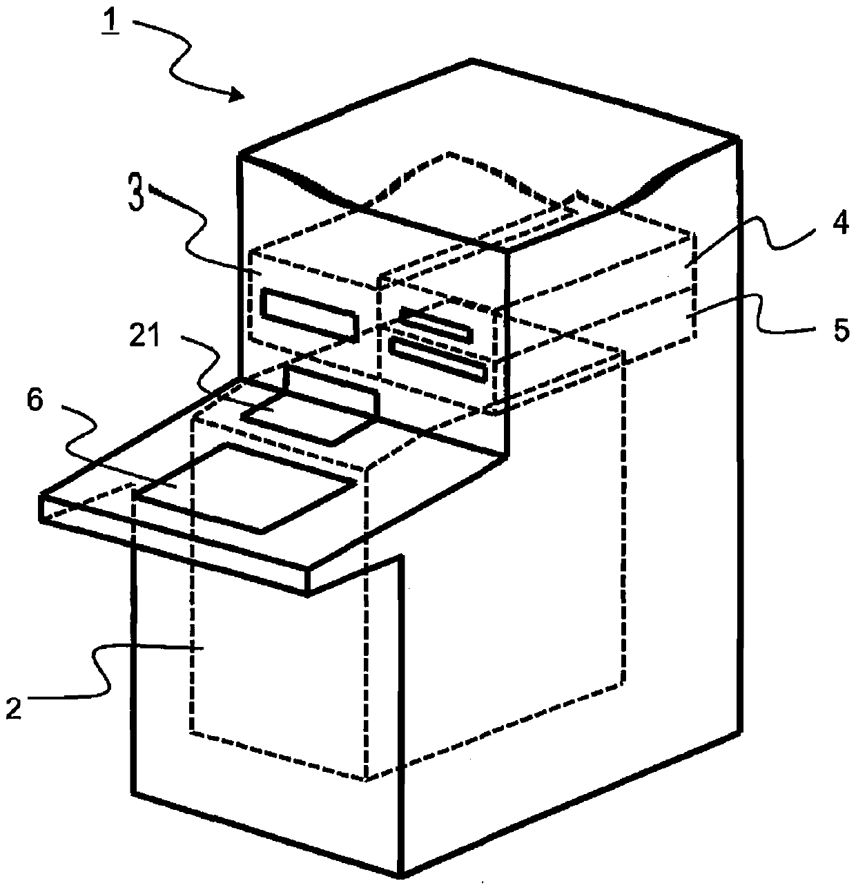
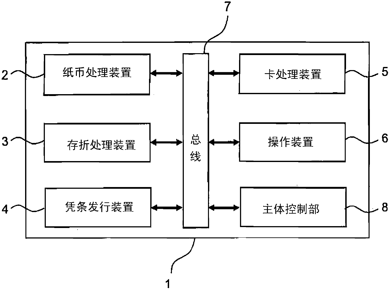
[0029] figure 1 It is a perspective view of the appearance of a cash automatic teller machine. The cash automatic teller machine 1 is constituted by a banknote processing device 2 , a passbook processing device 3 , a receipt issuing device 4 , a card processing device 5 , and an operating device 6 .
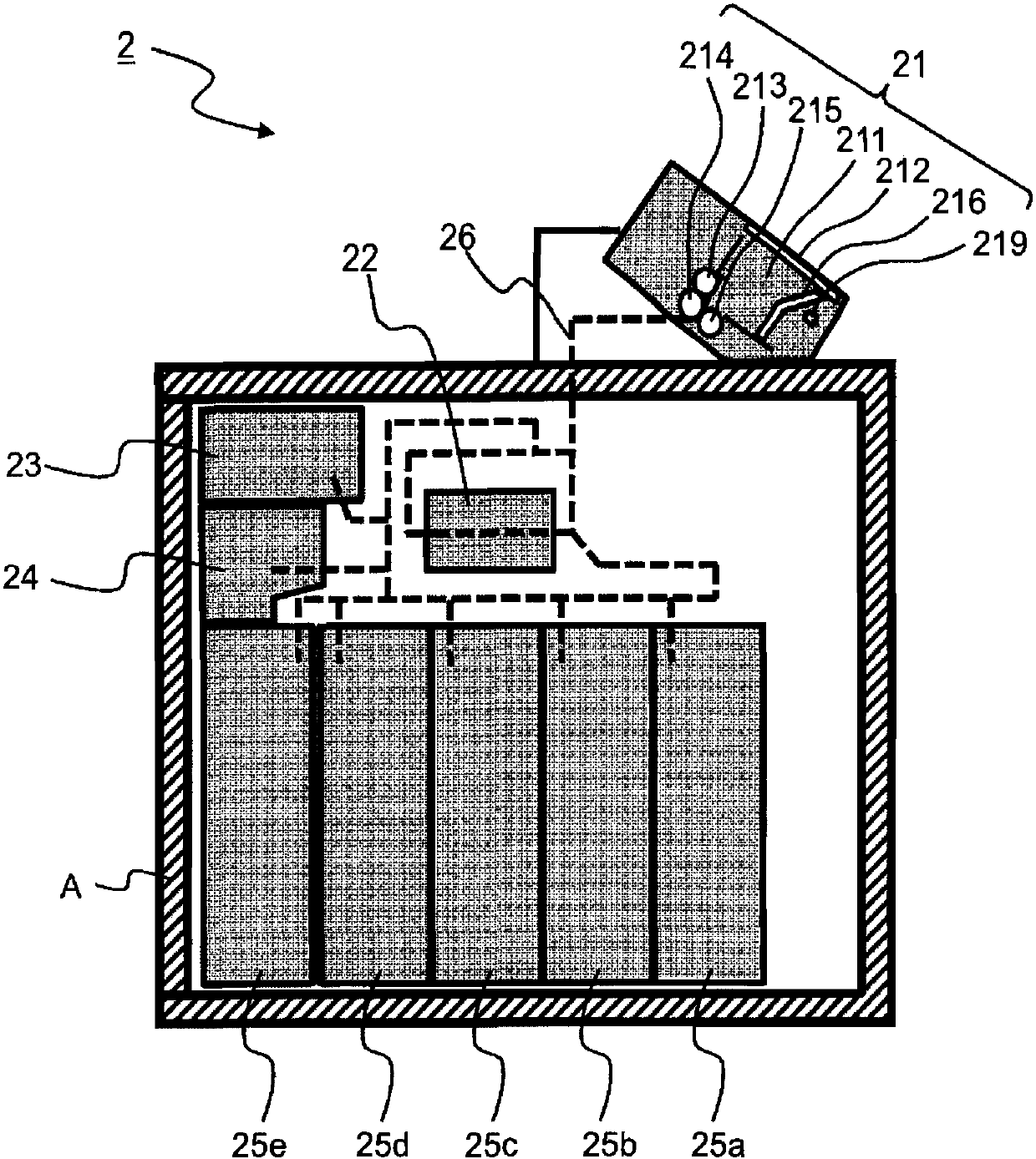
[0030] The banknote handling device 2 is a device for handling banknotes. The banknote processing apparatus 2 executes banknote deposit processing, withdrawal processing, identification processing, and the like through the deposit and withdrawal port 21 through which a user inserts banknotes and discharges banknotes to the user. Moreover, the banknote storage for storing banknotes is provided in the lower part of the banknote handling apparatus 2, and the banknote storage is surrounded by a safe box. The detailed configuration of the banknote handling device will be described later.
[0031] In the deposit transaction of the cash automatic teller machine 1, the banknote handli...
Embodiment 2
[0072] Hereinafter, the second embodiment will be described in detail. This embodiment differs from the first embodiment in the structure of the permeable portion 216c of the pressure plate 216, but the other structures are the same as those of the first embodiment.
[0073] Part of the transmissive portion 216c in the present embodiment is printed with patterns symbolizing banknotes, arrows, etc. on a plate made of a transparent material fitted into the platen 216, and visible light is blocked in the printed area. That is, in the case where the unprinted portion of the transmissive portion 216c is defined as the first portion and the printed portion is defined as the second portion, the visible light transmittance of the second portion becomes lower than that of the first portion. Low. In addition, in the processing of the region corresponding to the second portion, in addition to printing using a dot pattern or the like in order to scatter light, methods other than printing...
Embodiment 3
[0077] Hereinafter, the third embodiment will be described in detail. This embodiment differs from the first embodiment in the structure of the shutter 212, but other structures are common to the first embodiment.
[0078] Figure 11 It is a figure explaining the detailed structure of the deposit and withdrawal port in this embodiment. The shutter 212 has a structure including a transmission portion 212a that transmits a part of visible light. When the shutter 212 is in the closed state, light is irradiated by the irradiation mechanism 219, and a part of the light passes through the transmission part 212a, and can be used as an instruction lamp for guiding the banknote insertion position. In addition, more clear guidance can be performed by printing a pattern, an arrow, etc. as described in the second embodiment, or performing a process of scattering light on the transmissive portion 212a.
[0079] Thus, by providing the transparent part 212a in the shutter 212, before a us...
PUM
 Abstract
Description
Claims
Application Information
 - R&D
- Intellectual Property
- Life Sciences
- Materials
- Tech Scout
- Unparalleled Data Quality
- Higher Quality Content
- 60% Fewer Hallucinations
Browse by: Latest US Patents, China's latest patents, Technical Efficacy Thesaurus, Application Domain, Technology Topic, Popular Technical Reports.
© 2025 PatSnap. All rights reserved.Legal|Privacy policy|Modern Slavery Act Transparency Statement|Sitemap|About US| Contact US: help@patsnap.com


