Liquid crystal display driving system and liquid crystal display driving method

A liquid crystal display and driving system technology, applied in static indicators, instruments, etc., can solve the problems of poor display effect, uneven brightness, and bright brightness of the liquid crystal display panel, and achieve the effect of avoiding uneven display brightness

Active Publication Date: 2016-02-03
TCL CHINA STAR OPTOELECTRONICS TECH CO LTD
View PDF8 Cites 12 Cited by
  • Summary
  • Abstract
  • Description
  • Claims
  • Application Information

AI Technical Summary

Problems solved by technology

[0003] However, the difference in brightness in areas with low grayscale (for example, below grayscale 10) is very obvious. When the moiré phenomenon is serious, the compensation value used is relatively large. In this case, the dev

Method used


Image

  • Liquid crystal display driving system and liquid crystal display driving method
  • Liquid crystal display driving system and liquid crystal display driving method

Examples


Embodiment Construction

[0028] The following will clearly and completely describe the technical solutions in the embodiments of the present invention with reference to the accompanying drawings in the embodiments of the present invention. Obviously, the described embodiments are only some, not all, embodiments of the present invention. Based on the embodiments of the present invention, all other embodiments obtained by persons of ordinary skill in the art without making creative efforts belong to the protection scope of the present invention.

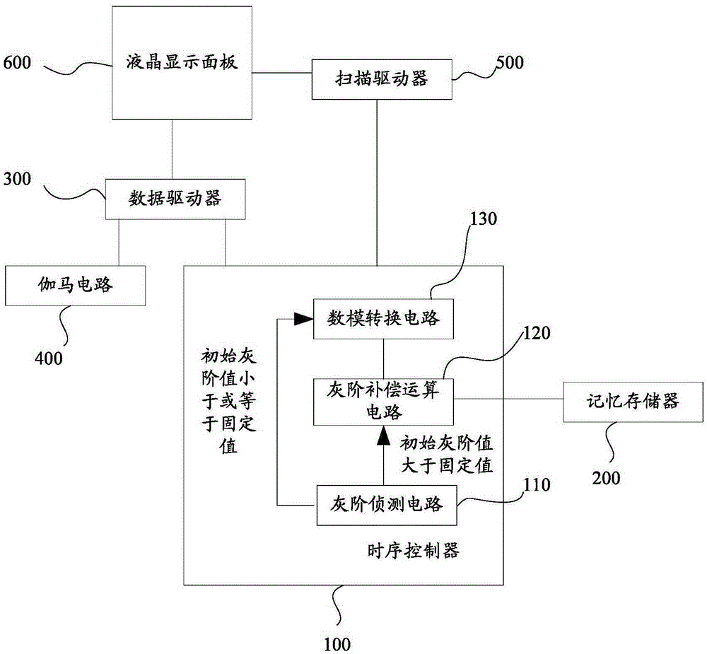
[0029] see figure 1 , figure 1 It is a schematic circuit diagram of the liquid crystal display driving system in the first embodiment of the present invention. In the first embodiment of the present invention, the liquid crystal display drive system includes a timing controller 100 and a memory storage 200, the timing controller 100 is connected to the memory storage 200, and the timing controller 100 is used to read the The gray scale compensation value in ...


PUM


Abstract

The invention discloses a liquid crystal driving system. The liquid crystal driving system comprises a sequence controller and a memory storage device, the sequence controller is used for reading a gray-scale compensation value in the memory storage device and obtaining a correction gray-scale value according to the gray-scale compensation value and an initial gray-scale value from a host system, the sequence controller comprises a gray-scale detection circuit and a gray-scale compensation operation circuit, the gray-scale detection circuit is used for detecting whether the initial gray-scale value of the host system is smaller than or equal to a fixed value, and the sequence controller regards the initial gray-scale value as the correction gray-scale value when the initial gray-scale value is smaller than or equal to the fixed value. According to the liquid crystal display driving system, the phenomenon of non-uniform display brightness caused by low gray-scale compensation of a liquid crystal display panel can be avoided. The invention also discloses a liquid crystal driving method.

Description


Claims


Application Information

Patent Timeline
Owner TCL CHINA STAR OPTOELECTRONICS TECH CO LTD
Why Eureka
Try Eureka