
Pixel driving circuit, driving method therefor and display device

A technology of pixel drive circuit and drive module, applied in static indicators, instruments, etc., which can solve problems such as reducing the quality and quality of display screens, affecting display brightness uniformity and brightness constancy, and changing the current of OLED devices

Active Publication Date: 2016-03-23
BOE TECH GRP CO LTD +1
View PDF5 Cites 7 Cited by
  • Summary
  • Abstract
  • Description
  • Claims
  • Application Information

AI Technical Summary

Problems solved by technology

However, due to the production process and the characteristics of polysilicon, when the TFT switch circuit is fabricated on a large-area glass substrate, there are often fluctuations in electrical parameters such as threshold voltage Vth, mobility, etc., so that the flow through the OLED device in the AMOLED display panel The current will not only change with the change of the on-voltage stress generated by the long-time conduction of the TFT, but also vary with the drift of the threshold voltage Vth of the TFT
In this way, it will affect the brightness uniformity and brightness constancy of the display
Thereby reducing the picture quality and quality of the display

Method used


Image

  • Pixel driving circuit, driving method therefor and display device
  • Pixel driving circuit, driving method therefor and display device
  • Pixel driving circuit, driving method therefor and display device

Examples


Embodiment Construction

[0030] The following will clearly and completely describe the technical solutions in the embodiments of the present invention with reference to the accompanying drawings in the embodiments of the present invention. Obviously, the described embodiments are only some, not all, embodiments of the present invention. Based on the embodiments of the present invention, all other embodiments obtained by persons of ordinary skill in the art without making creative efforts belong to the protection scope of the present invention.

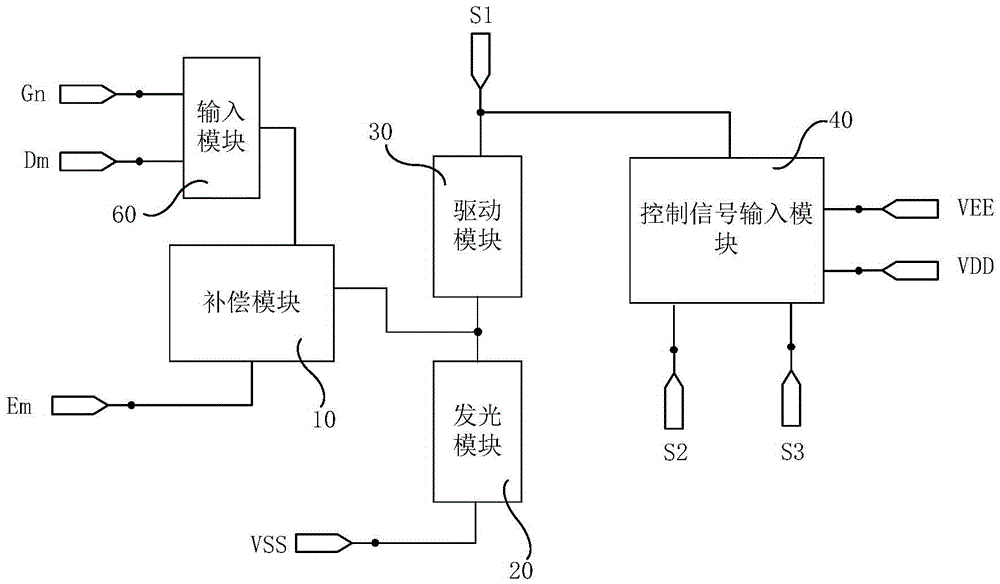
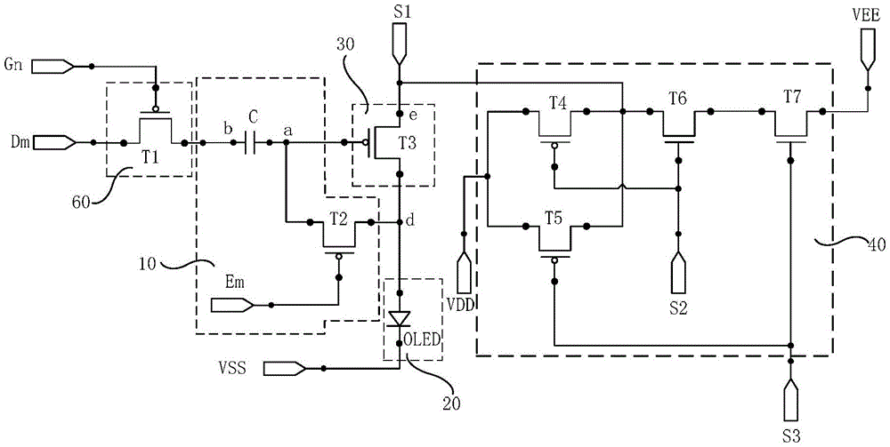
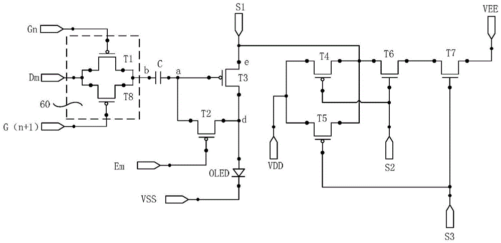
[0031] An embodiment of the present invention provides a pixel driving circuit, such as figure 1As shown, it may include an input module 60 , a compensation module 10 , a driving module 30 , a light emitting module 20 and a control signal input module 40 .

[0032] Wherein, the input module 60 is connected to the first gate signal terminal Gn, the data voltage terminal Dm and the compensation module 10 for outputting the signal of the data voltage terminal Dm ...


PUM


Abstract

An embodiment of the invention provides a pixel driving circuit, a driving method therefor and a display device; wherein the pixel driving circuit, the pixel driving method and the display device relate to the technical field of displaying. The pixel driving circuit, the driving method therefor and the display device can prevent a defect of display brightness non-uniformity of a display device caused by a threshold voltage. The pixel driving circuit comprises an input module, a compensation module, a driving module, a light emitting module and a control signal input module. The input module is controlled by a first gate signal end and is used for outputting the signal of a data voltage end to the compensation module. The compensation module is controlled by the input module and a threshold voltage control end and is used for compensating the threshold voltage of the driving module. The light emitting module is controlled by a first control signal end and is used for driving the light emitting module to emit light. The control signal input module is controlled by a second control signal end and a third control signal end and is used for outputting the signal of the second voltage end or the third voltage end to the first control signal end. The pixel driving circuit, the driving method therefor and the display device are used for driving a pixel unit to emit light.

Description

technical field [0001] The present invention relates to the field of display technology, in particular to a pixel driving circuit, a driving method thereof, and a display device. Background technique [0002] With the rapid progress of display technology, semiconductor element technology, which is the core of the display device, has also been greatly improved. For existing display devices, organic light emitting diode (OrganicLightEmittingDiode, OLED), as a current-type light-emitting device, is more and more popular because of its characteristics such as self-illumination, fast response, wide viewing angle and the ability to be fabricated on a flexible substrate. It is increasingly used in the field of high-performance display. [0003] According to the driving method, OLED can be divided into two types: PMOLED (PassiveMatrixDrivingOLED, passive matrix driving organic light emitting diode) and AMOLED (ActiveMatrixDrivingOLED, active matrix driving organic light emitting di...

Claims


Application Information

Patent Timeline
IPC IPC(8): G09G3/3258G09G3/3291
CPCG09G3/3258G09G3/3291G09G3/3233G09G2300/0814G09G2300/0819G09G2300/0871G09G2320/0233
Inventor 王光兴张斌董殿正张强张衎
Owner BOE TECH GRP CO LTD
Learn More