Power distribution cabinet with good dustproof and ventilation properties

A power distribution cabinet, performance technology, applied in substation/power distribution device shell, substation/switchgear cooling/ventilation, electrical components, etc., can solve the problem of poor dustproof effect, poor heat dissipation effect, power distribution cabinet electrical The problem of component burnout and other problems is achieved, and the effect of good dustproof and ventilation performance, good heat dissipation effect and good dustproof effect is achieved.

Inactive Publication Date: 2016-02-03
曾凯涛
View PDF0 Cites 10 Cited by
  • Summary
  • Abstract
  • Description
  • Claims
  • Application Information

AI Technical Summary

Problems solved by technology

[0002] Due to sunlight and self-heating of the outdoor power distribution cabinet, the temperature inside the cabinet is likely to rise, and what is more, it will cause the electrical components inside the power distribution cabinet to burn out. In order to prevent this from happening, the existing power distribution cabinet The cabinet generally punches louvers on the side wall of the power distribution cabinet, then adds a cover, and adds a filter to the louvers
This kind of power distribution cabinet is only ventilated through the shutters, and the power distribution cabinet can only dissipate heat locally. , its dust-proof effect is not good, and it is easy to affect the normal operation of the equipment; if the power distribution cabinet installed on the roadside or in the green belt uses this structure, when the sprinkler passes by or it rains, water can easily enter the distribution cabinet from the shutters. In the electric cabinet, the electrical components in the power distribution cabinet are burned, causing unnecessary losses

Method used


Image

  • Power distribution cabinet with good dustproof and ventilation properties
  • Power distribution cabinet with good dustproof and ventilation properties
  • Power distribution cabinet with good dustproof and ventilation properties

Examples


Embodiment Construction

[0017] The following will clearly and completely describe the technical solutions in the embodiments of the present invention with reference to the accompanying drawings in the embodiments of the present invention. Obviously, the described embodiments are only some, not all, embodiments of the present invention. Based on the embodiments of the present invention, all other embodiments obtained by persons of ordinary skill in the art without making creative efforts belong to the protection scope of the present invention.

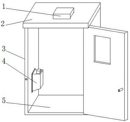
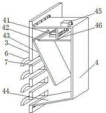
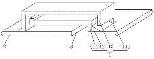
[0018] see Figure 1-4 , the present invention provides a technical solution: a power distribution cabinet with good dustproof and ventilation performance, including a power distribution cabinet body 5, a power distribution cabinet body 5 including a top cover 2 and a side plate 3, and a box door of the power distribution cabinet body 5 There is an observation window on the top to facilitate the observation of the inside of the power distribution cabinet body ...


PUM


Abstract

The invention discloses a power distribution cabinet with good dustproof and ventilation properties, which comprises a power distribution cabinet body, wherein the power distribution cabinet body comprises a top cover and a side plate and is characterized in that an air outlet is disposed in the surface of the top cover, an air outlet device is connected on the upper surface of the top cover by bolts, the air outlet is located inside the air outlet device, a plurality of air inlet troughs are disposed in the side plate, arc baffles are disposed on the outer sides of the multiple air inlet troughs, an air inlet device is connected to the inner side of the side plate by bolts, and the air inlet device is corresponding to the air inlet troughs. In the power distribution cabinet with the good dustproof and ventilation properties, the air inlet device and the air outlet device are disposed at different positions, so that convection can be formed inside the power distribution cabinet body and ventilation and heat dissipation effects are better. Cavities formed by the baffles can isolate the inside of the power distribution cabinet body from external air. Filtering holes in a filtering tube can filter large dust particles and filtration of a filter screen is then carried out, so filtering effects are better.

Description

technical field [0001] The invention relates to the technical field of power equipment, in particular to a power distribution cabinet with good dustproof and ventilation performance. Background technique [0002] Due to sunlight and self-heating of the outdoor power distribution cabinet, the temperature inside the cabinet is likely to rise, and what is more, it will cause the electrical components inside the power distribution cabinet to burn out. In order to prevent this from happening, the existing power distribution cabinet The cabinet generally punches louvers on the side wall of the power distribution cabinet, then adds a cover, and adds a filter screen to the louvers. This kind of power distribution cabinet is only ventilated through the shutters, and the power distribution cabinet can only dissipate heat locally. , its dust-proof effect is not good, and it is easy to affect the normal operation of the equipment; if the power distribution cabinet installed on the road...

Claims


Application Information

Patent Timeline
Patent Type & Authority Applications(China)
IPC IPC(8): H02B1/56H02B1/28
CPCH02B1/565H02B1/28
Inventor 曾凯涛
Owner 曾凯涛
Why Eureka
Try Eureka