Invisible television wall

A TV wall and TV technology, applied in the direction of walls, building components, covering/lining, etc., can solve the problems of wall damage, difficult to move, unable to adjust the height and angle of TV, and achieve the effect of saving indoor space

Inactive Publication Date: 2016-02-10
RENQIU YONGJI CONSTR & INSTALLATION ENG
View PDF9 Cites 4 Cited by
  • Summary
  • Abstract
  • Description
  • Claims
  • Application Information

AI Technical Summary

Problems solved by technology

For the wall-mounting of LCD TVs, it is necessary to drill holes on the wall and embed bolts and hangers to hang the LCD TVs. Although this method saves space, it has many shortcomings: ① After the LCD TV is installed, the TV height and height cannot be adjusted. Angle, and not easy to move; ②This method will cause irreversible damage to the wall
For LCD TV seat placement, although it can avoid damage to the wall, it needs to be equipped with TV cabinets or small tables, etc., which takes up a lot of indoor space, and the height and angle of the TV cannot be adjusted.

Method used


Image

  • Invisible television wall
  • Invisible television wall
  • Invisible television wall

Examples


specific Embodiment 1

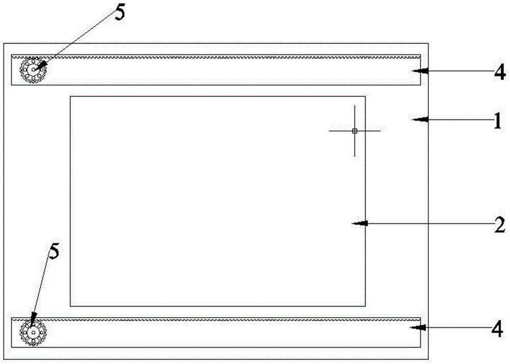
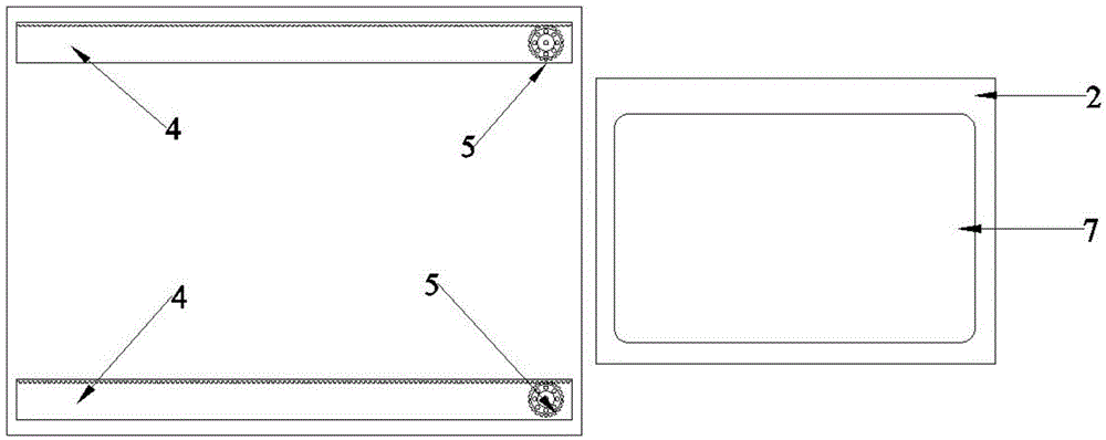
[0010] Specific embodiment 1: as figure 1 and figure 2 As shown, in the case of not watching TV, the wall is a clean and integral wall, and the TV blocking part 1 is visually integrated with the surrounding walls. When you need to watch TV, start the control switch, and the TV shielding part 1 will move left or right under the drive of the gear 5 and the rack 4, until the whole TV placement area 2 is exposed, and then stop moving. Then start the control switch, and the LCD TV 7 is driven by the connecting rod device to adjust its height and angle.

specific Embodiment 2

[0011] Specific embodiment 2: as Image 6 and Figure 7 As shown, in the case of not watching TV, there is a picture hanging on the wall; when it is necessary to watch TV, start the control switch, and the TV blocking part 1 is divided into left and right parts driven by the gear 5 and the rack 4, and the two parts are respectively left and right. Move and move right until the entire TV placement area is exposed, at which point the movement stops. Then start the control switch, and the LCD TV 7 is driven by the connecting rod device to adjust its height and angle.

specific Embodiment 3

[0012] Specific embodiment 3: as Figure 8 and Figure 9 As shown, in the case of not watching TV, there is a picture hanging on the wall; when it is necessary to watch TV, start the control switch, and the TV blocking part 1 is divided into upper and lower parts driven by the gear 5 and the rack 4, and the two parts go up and down respectively. Move up and down until the entire TV placement area is exposed, then stop moving. Then start the control switch, and the LCD TV 7 is driven by the connecting rod device to adjust its height and angle.

[0013] The invisible TV wall not only saves indoor space, but also the TV will only appear when the TV is needed, and the height and angle can be adjusted, which is suitable for the simple life of modern people.


PUM


Abstract

An invisible television wall comprises a television shielding part, a television placement area and a control switch. The television shielding part is a light cuboid baffle of a wall face or wallpaper same as a wall, a light integrated painting with a frame can be selected, a light painting capable of being divided into an upper part and a lower part or a left part and a right part can also be selected, and the overall area of the baffle needs to be larger than the area of the television placement area. A rack is installed on the back side of the television shielding part, a gear matched with the rack is installed on the wall, and the television shielding part can slide to a specified position through the arrangement of the gear and the rack. The television placement area is a concave area in the wall. A liquid crystal television is fixed to the inner wall of the television placement area through a connection rod device, the liquid crystal television can enter and get out of the television placement area, and the height of the liquid crystal television is adjustable. When people do no need to watch the television, the wall is a tidy and clean wall or a wall where a painting is hung. When people watch the television, the control switch is started, the television shielding part is removed, and the liquid crystal television gets out of the television placement area and is adjusted to a proper position.

Description

technical field [0001] The invention relates to the field of home furnishing, in particular to an invisible video wall. Background technique [0002] Nowadays, the TV sets of every family basically choose LCD TVs. Usually, there are two ways to install LCD TVs, one is wall-mounted, and the other is seated. For the wall-mounting of LCD TVs, it is necessary to drill holes on the wall and embed bolts and hangers to hang the LCD TVs. Although this method saves space, it has many shortcomings: ① After the LCD TV is installed, the TV height and height cannot be adjusted. Angle, and not easy to move; ②This method will cause irreversible damage to the wall. As far as the LCD TV is placed, although it can avoid damage to the wall, it needs to be equipped with a TV cabinet or a small table, which takes up a lot of space in the room, and the height and angle of the TV cannot be adjusted. Contents of the invention [0003] In order to overcome the above-mentioned shortcomings in the...

Claims


Application Information

Patent Timeline
Patent Type & Authority Applications(China)
IPC IPC(8): E04B2/00E04F13/074
Inventor 朱连吉孙玉娣
Owner RENQIU YONGJI CONSTR & INSTALLATION ENG
Why Eureka
Try Eureka