Rotary shaft with a vent groove

A technology of ventilation slots and rotating shafts, which is applied in the direction of shafts, shafts and bearings, mechanical equipment, etc., and can solve problems such as the inability to ensure the effect of airflow delivery

Inactive Publication Date: 2016-02-10
ACM RES SHANGHAI
View PDF7 Cites 6 Cited by
  • Summary
  • Abstract
  • Description
  • Claims
  • Application Information

AI Technical Summary

Problems solved by technology

The current structure of the rotating shaft does not guarantee the effect of airflow delivery

Method used


Image

  • Rotary shaft with a vent groove
  • Rotary shaft with a vent groove
  • Rotary shaft with a vent groove

Examples


Embodiment Construction

[0022] The above-described features and advantages of the present invention can be better understood after reading the detailed description of the embodiments of the present disclosure in conjunction with the following drawings. In the drawings, components are not necessarily drawn to scale and components with similar related characteristics or features may have the same or similar reference numbers.

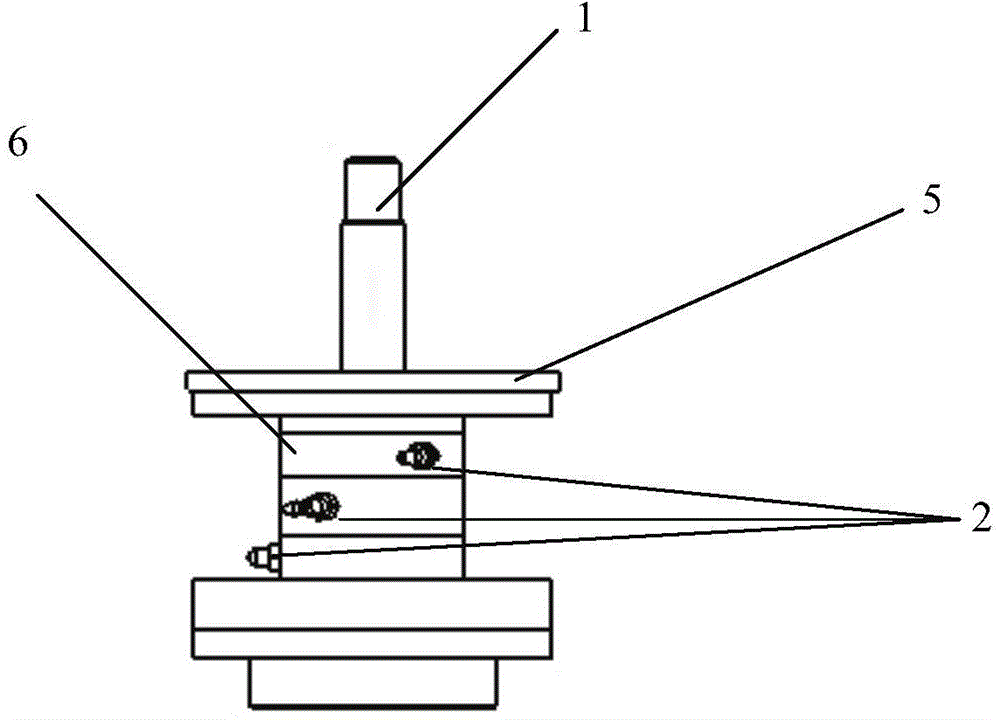
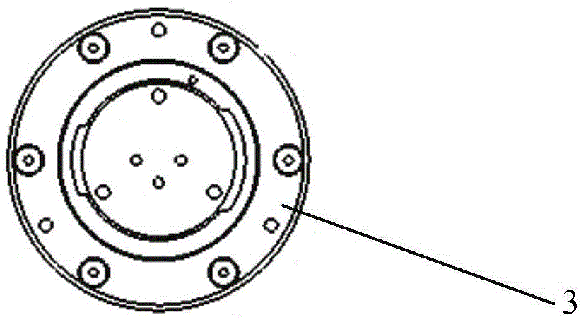
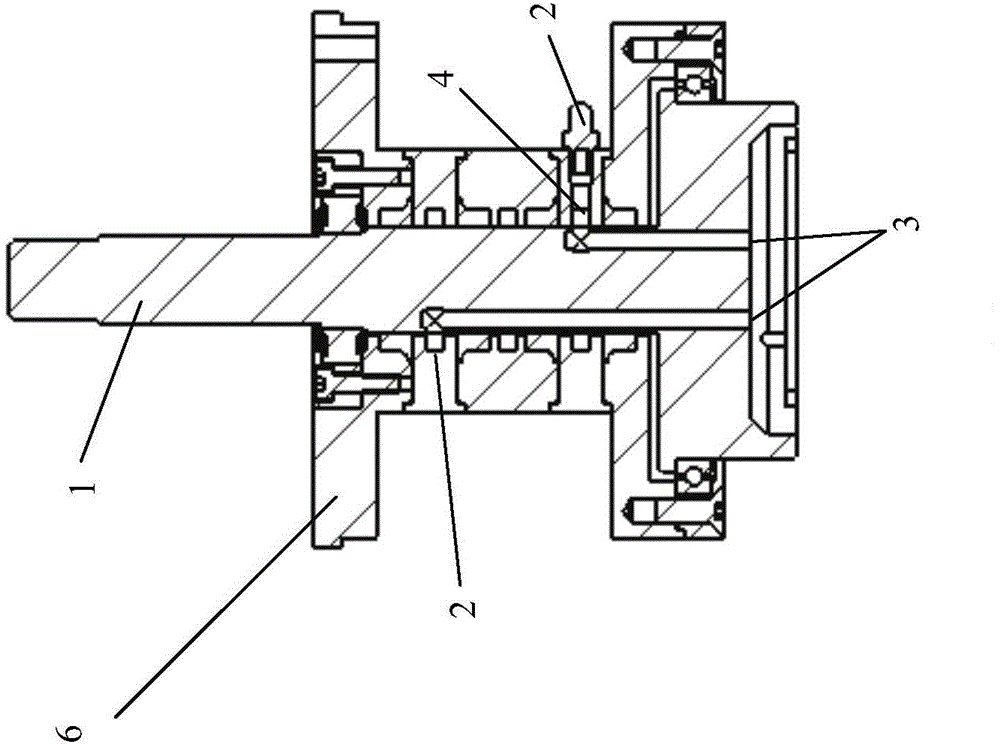
[0023] figure 1 The outline of the preferred embodiment of the rotating shaft with ventilation grooves of the present invention is shown, Figure 2A and 2B The cross-sectional structure of such a rotating shaft with ventilation grooves is shown separately. see also figure 1 , Figure 2A and 2B , the rotating shaft with ventilation groove in this embodiment includes a rotatable shaft body 1 with a ventilation groove inside, a shaft sleeve 6 with a fixed position, a multi-way air inlet 2 on the shaft sleeve, and an air guide ring in the shaft sleeve. Space 4, and multiple ai...


PUM


Abstract

The invention discloses a rotary shaft with a vent groove. Airflow can be conveyed into the vent groove in a rotary shaft body from air inlets in a fixed shaft sleeve. According to the technical scheme, air enters the vent groove through the air inlets in the shaft sleeve, is guided into the vent groove in the shaft body through annular air guiding space and is finally exhausted out of an air outlet in the bottom end of the shaft body. All air paths, communicated with the annular air guiding space, of the air inlets are independent in space and do not interfere with one another. One end of the vent groove is communicated with the annular air guiding space all the time, and therefore even though the shaft sleeve is fixed and the shaft body rotates always, the process that air is conveyed into the vent groove in the shaft body from the air inlets in the shaft sleeve cannot be influenced.

Description

technical field [0001] The present invention relates to a rotating shaft, in particular to a rotating structural device that requires air conduction. Background technique [0002] In the equipment involved in the semiconductor wafer process, components such as rotating shafts are usually used, and in some process flows, it is necessary to convey the air flow through the rotating shaft. The current structure of the rotating shaft cannot guarantee the effect of air conveying. SUMMARY OF THE INVENTION [0003] A brief summary of one or more aspects is presented below to provide a basic understanding of the aspects. This summary is not an exhaustive overview of all contemplated aspects and is neither intended to identify key or critical elements of all aspects nor attempt to delineate the scope of any or all aspects. Its sole purpose is to present some concepts of one or more aspects in a simplified form as a prelude to the more detailed description that is presented later. ...

Claims


Application Information

Patent Timeline
Patent Type & Authority Applications(China)
IPC IPC(8): F16L39/06F16C3/02
Inventor 杨宏超金一诺张怀东王坚王晖
Owner ACM RES SHANGHAI
Why Eureka
Try Eureka