Eureka AIR delivers breakthrough ideas for toughest innovation challenges, trusted by R&D personnel around the world.

Multi-frequency antenna for mobile terminal and electronic equipment employing multi-frequency antenna

A multi-frequency antenna and mobile terminal technology, which is applied to independent antenna unit combinations, antennas, and devices that enable antennas to work in different frequency bands at the same time, can solve problems such as inability to guarantee radiation performance, inability to guarantee simultaneous operation, and use restrictions, etc. Achieve the effect of saving hardware space, achieving compatibility, and good radiation effect

Inactive Publication Date: 2016-02-10
VIVO MOBILE COMM CO LTD
View PDF9 Cites 10 Cited by
  • Summary
  • Abstract
  • Description
  • Claims
  • Application Information

AI Technical Summary

Problems solved by technology

With the reduction of antenna space, especially the appearance of metal-framed mobile phones, radiators with one or more wires usually need to use relatively poor radiation space, which cannot guarantee ideal radiation performance in all frequency bands
If switch technology is used, although the best space can be utilized, simultaneous work cannot be guaranteed, and there are limitations in use

Method used


Image

  • Multi-frequency antenna for mobile terminal and electronic equipment employing multi-frequency antenna
  • Multi-frequency antenna for mobile terminal and electronic equipment employing multi-frequency antenna
  • Multi-frequency antenna for mobile terminal and electronic equipment employing multi-frequency antenna

Examples


Embodiment Construction

[0015] The following will clearly and completely describe the technical solutions in the embodiments of the present invention with reference to the accompanying drawings in the embodiments of the present invention. Obviously, the described embodiments are only some, not all, embodiments of the present invention. Based on the embodiments of the present invention, all other embodiments obtained by persons of ordinary skill in the art without creative efforts fall within the protection scope of the present invention.

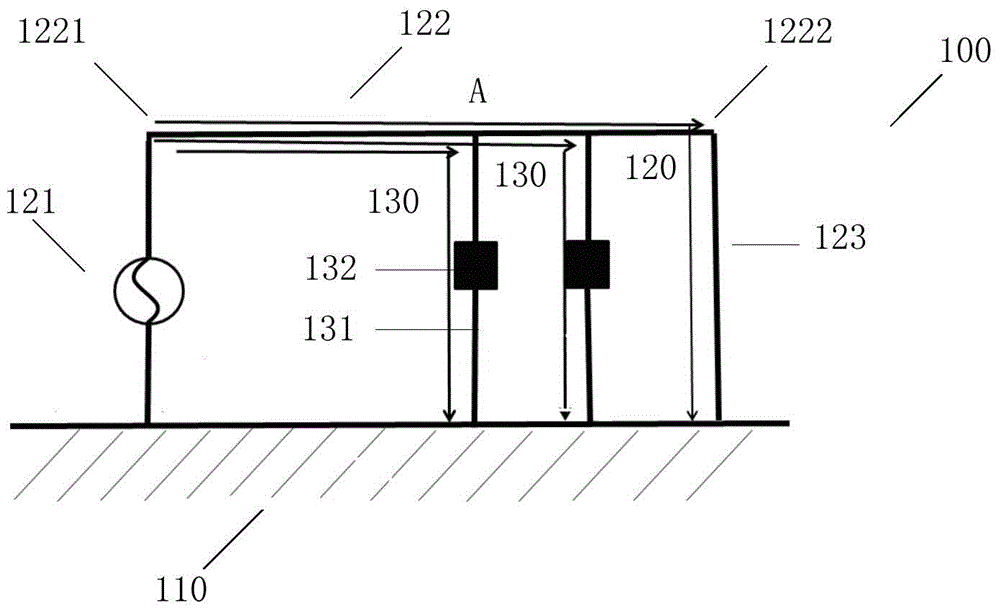
[0016] figure 1 , is a schematic structural diagram of a first embodiment of a multi-frequency antenna for a mobile terminal of the present invention, the antenna 100 includes: a metal floor 110, a first antenna loop 120 and at least one second antenna loop 130 ( figure 1 Take two as an example).

[0017] The metal floor 110 may be a main ground such as a screen bracket or a PCB board. The first antenna loop 120 includes a feed 121, a radiator 122 and a first bra...


PUM


Abstract

The invention relates to the field of mobile communication, and provides a multi-frequency antenna for a mobile terminal. The multi-frequency antenna comprises a metal floor, a first antenna loop and at least one second antenna loop. The embodiment of the invention further provides electronic equipment. According to the multi-frequency antenna, sharing utilization of an optimal radiator is achieved through a plurality of antenna loops; the hardware space is saved; meanwhile, the problem that a plurality of frequencies cannot coexist when an antenna switch is adopted is solved; the multi-band compatibility is achieved; and a good radiation effect is reached.

Description

technical field [0001] The invention relates to the field of mobile communication, in particular to a multi-frequency antenna for a mobile terminal and electronic equipment thereof. Background technique [0002] At present, mobile terminals are increasingly miniaturized and multi-frequency, which poses severe challenges to antenna design. Ordinary antennas need to have corresponding antenna branches to achieve dual-band or multi-band, which requires a high space for wiring. With the reduction of antenna space, especially the appearance of metal-frame mobile phones, radiators with one or more wires usually need to use relatively poor radiation space, which cannot guarantee ideal radiation performance in all frequency bands. If switch technology is used, although the best space can be utilized, simultaneous work cannot be guaranteed, and there are limitations in use. Contents of the invention [0003] In order to solve the above-mentioned problems in the prior art, an embo...

Claims


Application Information

Patent Timeline
Patent Type & Authority Applications(China)
IPC IPC(8): H01Q5/20H01Q23/00
CPCH01Q5/00H01Q21/30
Inventor 蒋锐
Owner VIVO MOBILE COMM CO LTD
Why Eureka
Eureka Blog
Learn More