
A downlink joint transmission control method, system and related device

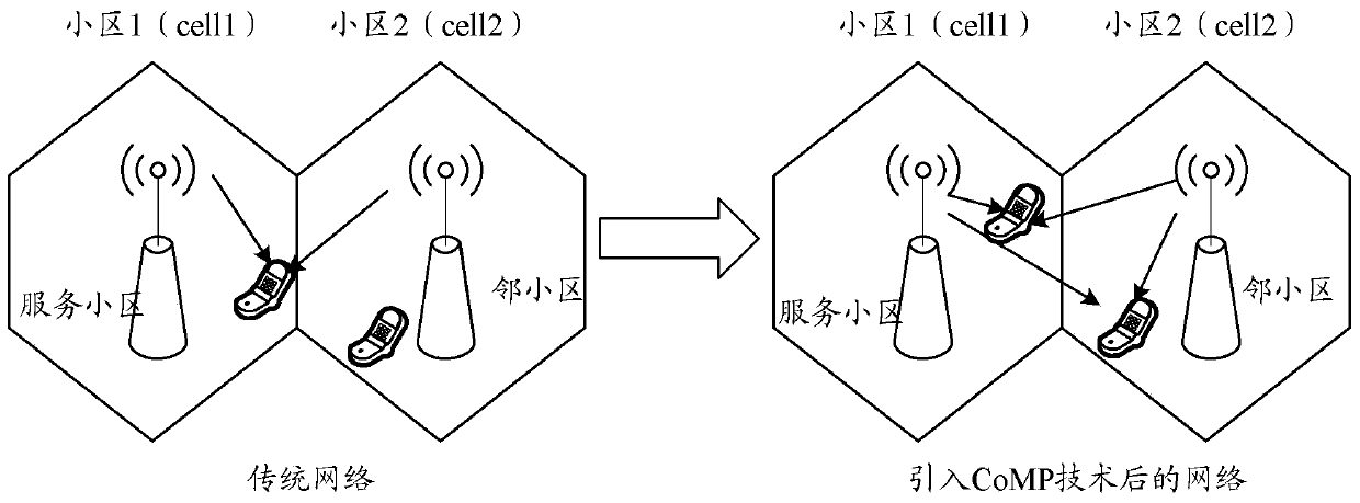
A joint transmission and control method technology, applied in the direction of wireless communication, electrical components, etc., can solve the problems of downlink service transmission rate drop and system transmission resource limitation, so as to solve the problem of limited interactive information transmission bandwidth and guarantee other system downlink services The effect of transfer rate

Active Publication Date: 2019-06-28
CHINA MOBILE COMM GRP CO LTD
View PDF5 Cites 0 Cited by
  • Summary
  • Abstract
  • Description
  • Claims
  • Application Information

AI Technical Summary

Problems solved by technology

However, in the actual live network deployment, this ideal situation does not exist
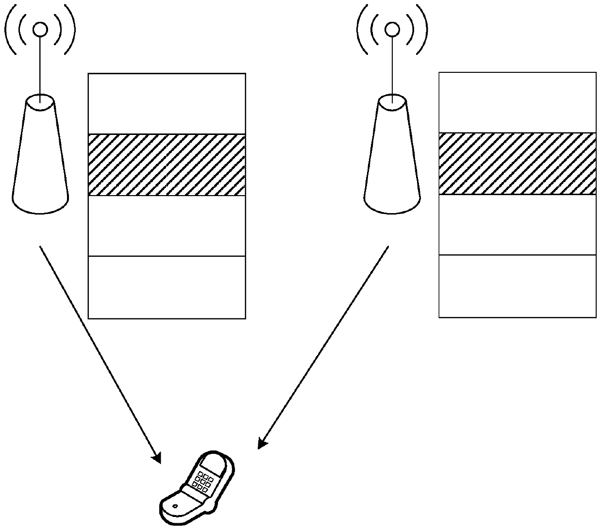
Therefore, since the transmission network resources are shared by multiple systems, the introduction of downlink JT technology may cause the transmission resources of other systems to be limited and the transmission rate of downlink services to decrease

Method used


Image

  • A downlink joint transmission control method, system and related device
  • A downlink joint transmission control method, system and related device
  • A downlink joint transmission control method, system and related device

Examples


specific Embodiment 1

[0093] Figure 5 It is a schematic diagram of the downlink joint transmission control flow described in Embodiment 1 of the present invention, as shown in Figure 5 As shown, the process includes:

[0094] Step 501: In a certain TTI, the serving cell receives CoMP measurement reporting events reported by multiple UEs.

[0095] Step 502: The serving cell selects a CoMP neighbor celli according to the strongest neighbor cell selection principle.

[0096] Step 503: The serving cell selects a CoMP UE from all UEs reporting celli.

[0097] 504: After selecting the CoMP UE, judge whether the transmission bandwidth of the existing interaction information is less than bMbps, if yes, go back to step 502; otherwise, go to step 505.

[0098] Step 505: The CoMP user selection within the TTI is completed, and the serving cell and each neighboring cell in the coordination set perform joint downlink transmission.

[0099] In this embodiment, the operations performed by the serving cell a...

specific Embodiment 2

[0100] Figure 6 It is a schematic diagram of the downlink joint transmission control flow described in Embodiment 2 of the present invention, as shown in Figure 5 As shown, the process includes:

[0101] Step 601: When a CoMP user is selected for the first time in each TTI, the serving cell clears the existing exchange information transmission bandwidth value.

[0102] Step 602: Judging whether there are multiple UEs reporting the neighboring cell for the selected strongest neighboring cell, if yes, execute step 603; otherwise, execute step 606.

[0103] Step 603: Determine whether the sum of the downlink service rates of these UEs plus the existing interaction information transmission bandwidth is less than bMbps, if yes, perform step 604; otherwise, perform step 605.

[0104] Step 604: Select these UEs as downlink JT CoMP UEs, add celli to the coordination set, add these UEs to the CoMP user set, and go to step 609.

[0105] Step 605: Delete the user with the highest do...


PUM


Abstract

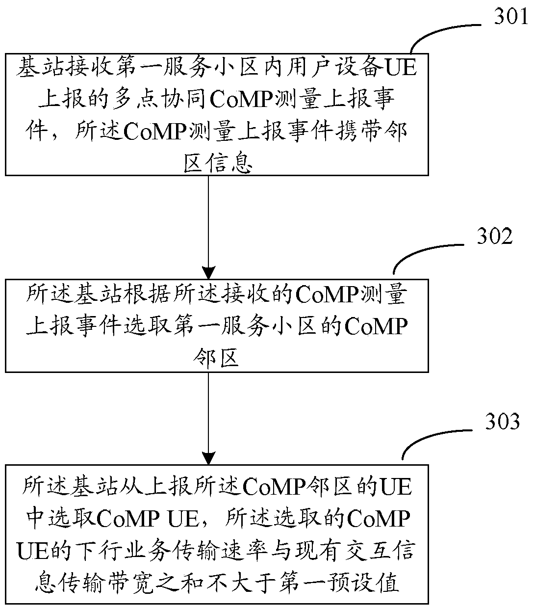
An embodiment of the invention discloses a method for controlling downlink JT (Joint Transmission), comprising the steps as follows: a base station receives a CoMP (Coordinated Multiple Points) measurement report event reported by UE (User Equipment) in a first serving cell, wherein the CoMP measurement report event carries adjacent cell information; the base station selects a CoMP adjacent cell of the first serving cell according to the received CoMP measurement report event; and selecting CoMP UE from the UE reporting the CoMP adjacent cell, wherein the sum of a downlink service transmission rate of the selected CoMP UE and a current interactive information transmission bandwidth is not more than a first preset value. The embodiment of the invention also correspondingly discloses a base station and a system for controlling downlink JT. According to the method and the system of the present invention, the CoMP UE is selected to control interactive information transmission bandwidth in a downlink JT technology, thus the problem of limited interactive information transmission bandwidth, which is not considered in the current scheme, can be solved, thereby avoiding downlink JT from occupying transmission resources of other systems, and ensuring downlink service transmission rates of the other systems.

Description

technical field [0001] The present invention relates to downlink joint transmission (JT) technology, in particular to a downlink joint transmission control method, system and related devices. Background technique [0002] The Time Division Long Term Evolution (TD-LTE) system adopts the same-frequency networking, and the same-frequency interference received by cell edge users from multiple neighboring cells is a problem that the TD-LTE system needs to solve. There are two main solutions to improve the co-channel interference of cell edge users: one is to adopt the solution of coordinating interference, and to coordinate the resource allocation of adjacent cells through inter-cell interference coordination (ICIC). resource allocation and power allocation) to avoid co-channel interference; another solution is to use interference signals, Coordinated Multiple Points (CoMP) technology introduces the cooperation of multiple sending / receiving nodes (such as interactive scheduling i...

Claims


Application Information

Patent Timeline
Patent Type & Authority Patents(China)
IPC IPC(8): H04W24/00H04W72/04
Inventor 旷婧华许宁龙紫薇邓伟
Owner CHINA MOBILE COMM GRP CO LTD
Learn More