Laser degumming device for shaft parts

A technology for shaft parts and shaft workpieces, which is applied in the field of laser degumming devices, can solve difficult problems and achieve the effects of wide application range, good feeding continuity and good degumming effect

Active Publication Date: 2017-05-10
SUZHOU TIANHONG LASER
View PDF9 Cites 0 Cited by
  • Summary
  • Abstract
  • Description
  • Claims
  • Application Information

AI Technical Summary

Problems solved by technology

In recent years, laser deglue is mainly used in areas such as electronic circuit boards, molds, car body paint removal and other plane-based fields. For example, small shaft parts such as motor shafts generally need to use glue during assembly. Once rework or It is very difficult to reinstall

Method used


Image

  • Laser degumming device for shaft parts
  • Laser degumming device for shaft parts
  • Laser degumming device for shaft parts

Examples


Embodiment Construction

[0018] Embodiments of the present invention will be further described below in conjunction with the accompanying drawings.

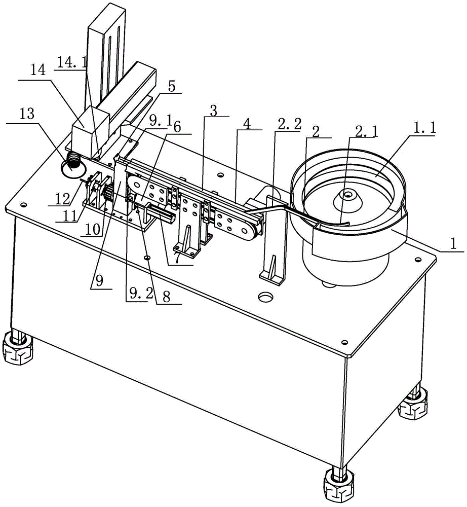
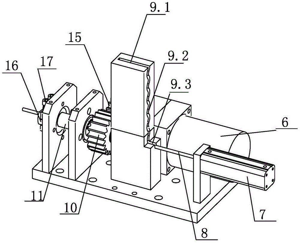
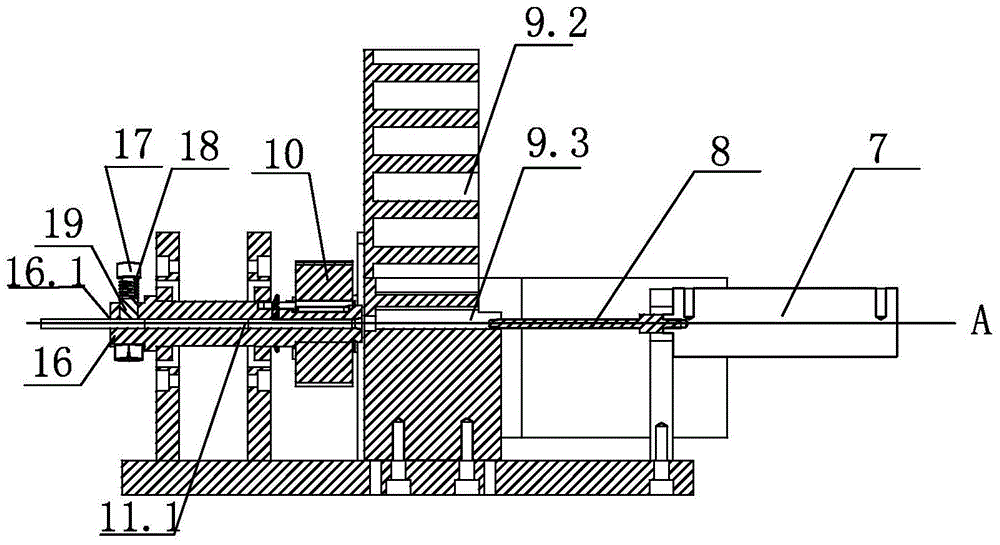
[0019] Such as Figure 1-3 As shown, a laser degumming device for shaft parts includes a control system, a vibrating plate feeding device 1 controlled by the control system, a belt transmission device, a feeding seat 9, an automatic pushing mechanism, a rotating tooling and Laser glue removal mechanism 14, the vibrating plate feeding device 1 includes a vibrating plate and a feeding track 2 located at the end of the vibrating plate, one end of the belt transmission device is directly connected to the described feeding track 2, The other end of the belt conveyor directly communicates with the feed opening 9.1 on the upper end of the discharge seat 9 (as figure 1 As shown, the feeding port 9.1 and the belt 3 are on the same axis), and the length of the feeding port 9.1 is greater than the length of the shaft workpiece; Channel 9.2, the described blanking...


PUM


Abstract

The invention discloses a laser glue removing device used for a shaft part. The laser glue removing device comprises a control system, a vibration plate feeding device, a belt conveying device, a discharging seat, an automatic material pushing mechanism, a rotating tool and a laser glue removing mechanism. The other end of the belt conveying device is directly communicated with a feeding port in the upper end of the discharging seat. The discharging seat is provided with a discharging channel for the shaft part to slide downwards. A discharging hole which is transversely-through is formed in the tail end of the discharging channel. The rotating tool comprises a rotating shaft and a driving mechanism used for driving the rotating shaft to rotate. One side of the discharging hole right corresponds to the tail end of a material pushing rod of a material pushing device, a discharging channel communicated with the other side of the discharging hole is formed in the rotating shaft in the axial direction in a penetrating manner, and the material pushing rod, the discharging hole and the discharging channel are located on the same horizontal axis A. The discharging end of the discharging channel of the rotating shaft is arranged under the laser glue removing mechanism. The laser glue removing device is specially used for the shaft part and is good in glue removing effect and controllability.

Description

technical field [0001] The invention relates to the field of laser equipment, in particular to a laser glue removal device for shaft parts. Background technique [0002] At present, for metal degumming and other degumming needs, low-end products generally adopt mechanical removal methods. However, the stress generated by the mechanical method greatly destroys the product yield and appearance, and affects the quality of the product. There are also chemical glue removal methods in the industry, but the problem is that chemical glue removal methods also have disadvantages such as polluting the environment, low safety factor, and high labor intensity. As an emerging surface degumming technology, laser degumming has many unique advantages, such as high degumming precision, good control, no contact with working materials, etc., and is superior to traditional degumming technology in some fields. In recent years, laser deglue is mainly used in areas such as electronic circuit boar...

Claims


Application Information

Patent Timeline
Patent Type & Authority Patents(China)
IPC IPC(8): B23K26/36B23K26/70B23K26/142
CPCB23K26/36
Inventor 陈磊余建平王涛
Owner SUZHOU TIANHONG LASER
Why Eureka
Try Eureka