Supercharge Your Innovation With Domain-Expert AI Agents!

Positioning jig for in-mold injection-molded steel sheets

A positioning fixture and in-mold injection molding technology, applied in the direction of coating, etc., can solve the problems of steel sheet deviation and movement, the manipulator is not in the correct position, and the degree of freedom of the manipulator cannot be limited.

Active Publication Date: 2017-07-28
东莞华誉精密技术有限公司
View PDF4 Cites 0 Cited by
  • Summary
  • Abstract
  • Description
  • Claims
  • Application Information

AI Technical Summary

Problems solved by technology

However, due to the cooperative positioning of the positioning post and the positioning hole, the degree of freedom of the manipulator along the radial direction of the positioning post can only be limited, and the degree of freedom of the manipulator along the axial direction of the positioning post cannot be restricted. When the manipulator is subjected to a force along the axial direction of the positioning post , the rigidity of the manipulator is not enough, and because there is no corresponding component to limit it, the manipulator may move along the axial direction of the positioning column, so that the manipulator will move when it is stressed, and the manipulator is not in the correct position, so when placing the steel sheet The phenomenon that the steel sheet deviates from the injection mold
When the steel sheet deviates from the injection mold, it is often necessary to manually adjust the position of the steel sheet, which greatly affects the production efficiency

Method used


Image

  • Positioning jig for in-mold injection-molded steel sheets
  • Positioning jig for in-mold injection-molded steel sheets
  • Positioning jig for in-mold injection-molded steel sheets

Examples


Embodiment 1

[0036] The preferred embodiments of the present invention will be described below in conjunction with the accompanying drawings. It should be understood that the preferred embodiments described here are only used to illustrate and explain the present invention, and are not intended to limit the present invention.

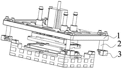
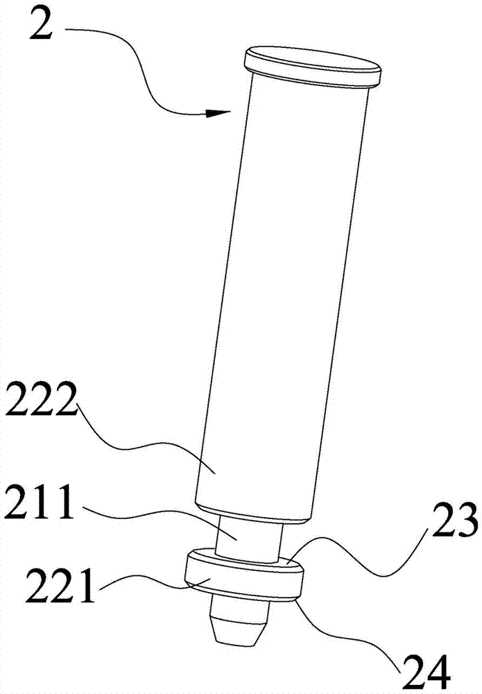
[0037] The positioning fixture of the inner injection molded steel sheet of the present invention, such as figure 1 As shown, it includes a base plate 1 and a positioning column 2, one end of the positioning column 2 is fixed to the base plate 1 by a screw, and the other end of the positioning column 2 is facing the injection mold 4 for the required positioning (see Figure 5 As shown) one end is provided with a stepped shaft. Such as figure 2 As shown, the machining of the stepped shaft is simple, just cut off a part of the commonly used positioning column and form the journal. Such as Figure 5 As shown, the positioning jig also includes a positioning insert 3...

Embodiment 2

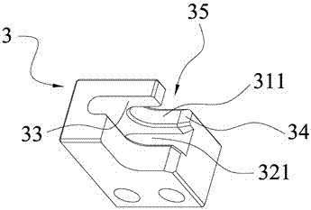
[0041] Embodiment 2 of the positioning fixture for injection molding steel sheets in the present invention, the main technical scheme of this embodiment is the same as that of Embodiment 1, and the features not explained in this embodiment adopt the explanation in Embodiment 1, here No further details will be given. The difference between this embodiment and embodiment 1 is that, as Figure 7 As shown, the stepped shaft includes a first journal 211, a second journal 212 and three shaft bodies respectively located on the sides of the two journals, and the three shaft bodies are respectively the first shaft body 221 and the second shaft body 222 And the third shaft body 223, the two shaft bodies near the end of the stepped shaft are the first shaft body 221 and the second shaft body 222; as Figure 8 As shown, the stepped groove includes two journal grooves and two axle body grooves, which are respectively a first journal groove 311 , a second journal groove 312 , a first axle ...


PUM


Abstract

The invention belongs to the field of positioning jigs, and particularly relates to a positioning jig for an injection molding steel sheet in a mould. A positioning part of the positioning jig refers to positioning posts and positioning inserts mounted on the mould. The tail sections of the positioning posts are set to be step shafts; meanwhile, the positioning inserts are also set to be step grooves with step structures; during positioning, the step shafts are translated into the step grooves from side openings in the positioning inserts; and shaft diameters of parts on the step shafts are different, and the step shafts are resisted against the step grooves, so that degree of freedom, in an axial direction of the positioning posts, of the positioning posts is restricted. In working, force, commonly born by the positioning jig, is in the axial direction of the positioning posts; and by matching with the step shafts with the step grooves, the positioning jig restricts the degree of freedom, in the axial direction of the positioning posts, of the positioning posts, so that the positioning stability of the positioning jig is improved.

Description

technical field [0001] The invention belongs to the field of positioning fixtures, in particular to a positioning fixture for injection molding steel sheets in a mold. Background technique [0002] With the rapid development of the electronics industry, people have higher and higher requirements for electronic products, especially for ultra-thin electronic products, which have been developing in the direction of super-large cross-section and ultra-thin body, and gradually ultra-thin electronic products The thin rubber part cannot meet the requirements of product strength. In order to meet the overall strength requirements of ultra-thin products, in-mold injection-molded steel sheets are often used to ensure the strength of the product. [0003] In-mold injection molding steel sheet is to put the steel sheet into the injection mold, and then close the mold and seal the glue to complete the manufacturing process of the in-mold injection molding steel sheet. The structure of t...

Claims


Application Information

Patent Timeline
Patent Type & Authority Patents(China)
IPC IPC(8): B29C45/14
CPCB29C45/14065
Inventor 胡明辉吴番宁
Owner 东莞华誉精密技术有限公司
Features
  • R&D
  • Intellectual Property
  • Life Sciences
  • Materials
  • Tech Scout
  • Unparalleled Data Quality
  • Higher Quality Content
  • 60% Fewer Hallucinations
Learn More