Automatic sampler

A technology of automatic sampling and sample holder, applied in the direction of instruments, analysis materials, etc., can solve the problems of cumbersome operation and achieve the effect of improving safety

Active Publication Date: 2016-02-17
SHIMADZU SEISAKUSHO CO LTD
View PDF4 Cites 3 Cited by
  • Summary
  • Abstract
  • Description
  • Claims
  • Application Information

AI Technical Summary

Problems solved by technology

[0003] However, because the sample rack located inside the autosampler can only be operated after the door 1 is removed, the operation is relatively cumbersome

Method used


Image

  • Automatic sampler
  • Automatic sampler
  • Automatic sampler

Examples


Embodiment Construction

[0026] Refer to the attached image 3 and Figure 4 An autosampler according to a preferred embodiment of the present invention will be described.

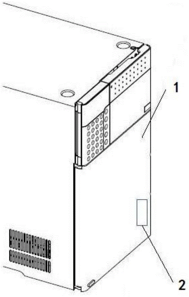
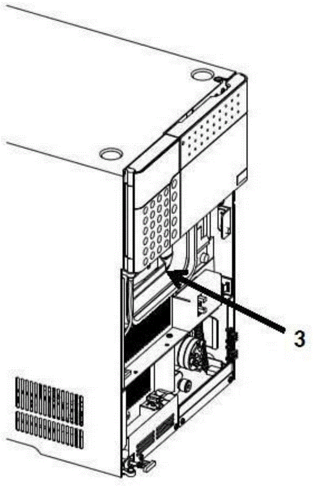
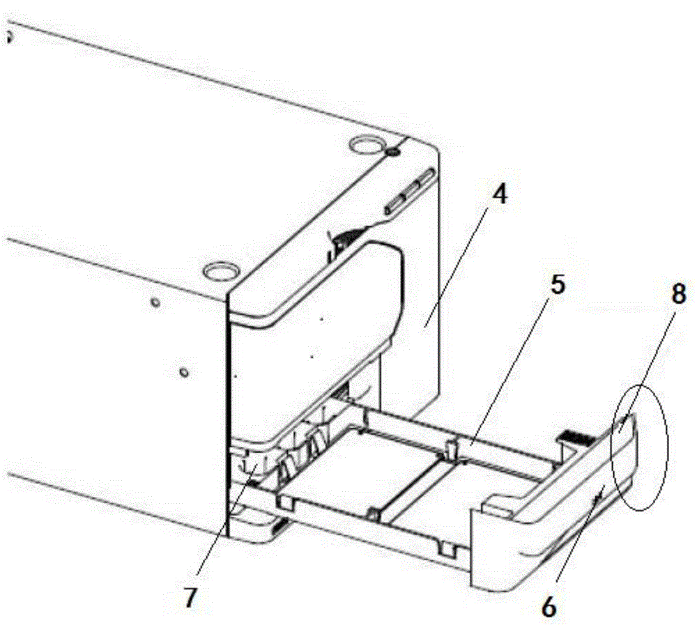
[0027] image 3 It is a schematic diagram of the state where the sample rack of the autosampler according to the embodiment of the present invention is pulled out. Figure 4 It is a schematic diagram of the fully inserted state of the sample rack of the autosampler according to the embodiment of the present invention.

[0028] Such as image 3 As shown, the autosampler includes a safety door 4 and a sample rack 5 with a handle 6 (an example of an operating part), and a rectangular opening 7 is provided on the safety door 4, and the operator can use the handle 6 to pass the sample rack 5 through the opening of the safety door 4. Opening 7 is inserted into the interior of the autosampler.

[0029] As a preferred embodiment of the present invention, such as image 3 As shown, the block-shaped handle 6 has a protrusion 8 integra...


PUM


Abstract

The invention relates to an automatic sampler. The automatic sampler comprises a safety door with an opening and a sample rack having an operation part, the operation part is used for passing the sample rack through the opening of the safety door and inserting the sample rack into the inner part of the automatic sampler or taking out the sample rack from the automatic sampler, under states that the safety door is closed and the sample rack is in an inserting state, the internal part and the external part of the automatic sampler are separated, under state that the sample rack is in the complete inserting state, the safety door cannot move by relating to the automatic sampler.

Description

technical field [0001] The invention relates to an automatic sample injector. Background technique [0002] In the existing technology, such as figure 1 As shown, an external structure of an autosampler is known. As a safety precaution for users, a door 1 is provided in front of the autosampler to completely close the front of the autosampler to prevent danger caused by hands etc. being inserted into the interior of the autosampler. A sensor 2 is disposed on the inner side of the door 1, and when the door 1 is removed, the sensor 2 can detect and stop the autosampler. After removing door 1, such as figure 2 As shown, the sample holder is inserted and pulled out through hole 3. [0003] However, since the sample rack located inside the autosampler can only be operated after the door 1 is removed, the operation is relatively cumbersome. Contents of the invention [0004] In order to improve the convenience of operation and further enhance the safety, the present invent...

Claims


Application Information

Patent Timeline
Patent Type & Authority Applications(China)
IPC IPC(8): G01N35/10
Inventor 朱鹏
Owner SHIMADZU SEISAKUSHO CO LTD
Why Eureka
Try Eureka