Circuitry for power limiting of electronic assembly

A power limitation and circuit device technology, applied in the field of circuit devices, can solve the problems of large-scale manufacturing, expensive, and differential dynamic characteristics of passive devices, and achieve the effect of achieving double security

Inactive Publication Date: 2011-06-29
MSA AUER GMBH
View PDF0 Cites 0 Cited by
  • Summary
  • Abstract
  • Description
  • Claims
  • Application Information

AI Technical Summary

Problems solved by technology

These zener diodes work very inaccurately as overvoltage protection or voltage limiting elements and as passive components are large and expensive to manufacture
In addition, a fuse connected downstream of the energy supply unit can blow out and thereby disable the circuit arrangement, so that the relevant electronic components can no longer be supplied with energy
The known circuit arrangement, which functionally limits the electronic components via the Zener diode, has a reduced operating time in battery operation due to its electrical power loss and the resulting poor dynamic behavior

Method used


Image

  • Circuitry for power limiting of electronic assembly
  • Circuitry for power limiting of electronic assembly
  • Circuitry for power limiting of electronic assembly

Examples


Embodiment Construction

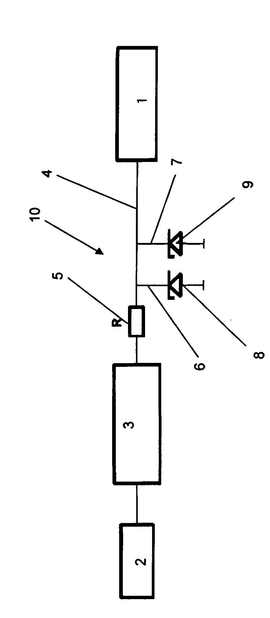
[0013] according to figure 1 A circuit arrangement according to the prior art for power limitation of electronic components comprises an energy supply unit 2 in the form of a battery with an output voltage of, for example, 3 V, a voltage boosting unit 3 for generating a higher voltage, for example of 5 V, in Output line 4 between voltage boosting unit 3 and electronic assembly 1, resistor 5 inserted into output line 4 and two parallel Zener diodes 8 inserted into lines 6, 7 branching from output line 4 ,9. The resistor 5 and the two zener diodes 8, 9 form a power limiting unit 10 for current limiting and voltage limiting.

[0014] Zener diodes 8 , 9 reduce the overvoltage generated by voltage boosting unit 3 in the event of a fault by means of heat that can only be dissipated with great effort. Zener diodes 8 , 9 work too inaccurately as voltage limiting elements and overvoltage protection elements and as passive components are large and expensive to manufacture. Furthermor...


PUM


Abstract

Circuitry for power limiting of an electronic assembly comprises units for power supplying, for voltage amplification and for power limiting. In known apparatus the power limiting unit is provided with resistors and Zener diodes which are only conditionally useful due to the large amount of heat occurring in case of a fault. The invention provides that the power limiting unit (27) has a voltage detector (31, 32) to determine any over-voltage and to output a switching signal if a threshold value of over-voltage is exceeded, and in the supply line (22) between the power supply unit (21) and the voltage amplifier unit (25) there is a switching element (23, 24) connected to the voltage detector (31, 32) via a switch-off line (29, 30).

Description

technical field [0001] The invention relates to a circuit arrangement for power limiting of electronic components, the circuit arrangement having an energy supply unit, a voltage boosting unit and a power limiting unit, the power limiting unit being connected to an output between the voltage boosting unit and the electronic component on the line. Such circuit arrangements are used, for example, by firefighters as motion detectors or safety control signaling devices against accidents. Background technique [0002] In the case of known circuit arrangements of this type for explosion protection in the event of overvoltage, the power limiting unit comprises a resistor inserted into the output line between the voltage boosting unit and the electronic assembly as a current limiting element and Consists of two parallel Zener diodes connected between the output line and ground as voltage limiting elements. They reduce the overvoltage generated by the voltage boosting unit in the e...

Claims


Application Information

Patent Timeline
IPC IPC(8): H02M1/32H02M3/07H02H9/00
CPCH02H9/008
Inventor 安德烈亚斯・莱姆克
Owner MSA AUER GMBH
Why Eureka
Try Eureka