
Cassette positioning device and semiconductor processing equipment

A technology for positioning devices and cassettes, applied in semiconductor/solid-state device manufacturing, electrical components, circuits, etc., can solve problems such as reduced transmission and process efficiency, wafer 6 offset, and manipulators cannot normally pick up wafers, etc., to avoid wafer position Offset or drop, ensure normal film pickup, improve transmission and process efficiency

Active Publication Date: 2016-02-17
BEIJING NAURA MICROELECTRONICS EQUIP CO LTD
View PDF4 Cites 8 Cited by
  • Summary
  • Abstract
  • Description
  • Claims
  • Application Information

AI Technical Summary

Problems solved by technology

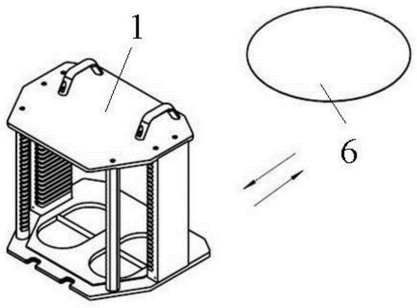
[0005] Because in the process of carrying the film cassette 1, the film cassette 1 will inevitably tilt and vibrate, which makes the wafer 6 easily shift outwards from the opening of the cassette 1, or even fall, thereby causing the manipulator to deviate due to the position of the wafer 6. Moved or dropped and cannot take the film normally, thus reducing the subsequent transmission and process efficiency

Method used


Image

  • Cassette positioning device and semiconductor processing equipment
  • Cassette positioning device and semiconductor processing equipment
  • Cassette positioning device and semiconductor processing equipment

Examples


no. 1 example

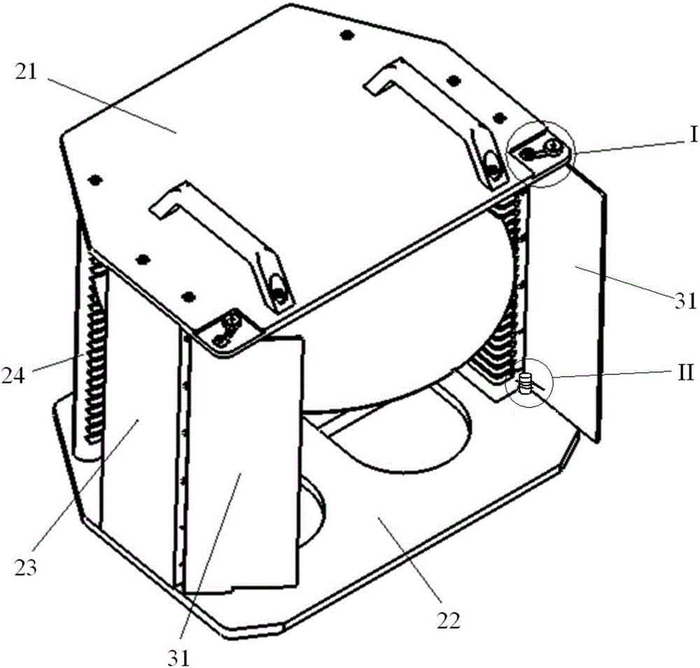
[0035] Please also refer to Figure 3A-Figure 4D , the sheet box is composed of a top plate 21, a bottom plate 22, a side frame 23 and a rear pillar 24. One side has an open frame structure with an opening (located on the side opposite to the rear pillar 24), and the inner surfaces of these parts are correspondingly provided with along the The multi-layer notches arranged at intervals in the vertical direction are used to support the wafer.

[0036] The cassette positioning device includes a limit gate 31 and a positioning mechanism. Wherein, there are two limit doors 31 , which are respectively rotatably connected to the two side frames 23 . By rotating the two limiting doors 31 synchronously, both of them can be located at the first position that blocks the movement of the wafers in the cassette, or at the second position that does not block the movement of the wafers in the cassette. The so-called second position of non-blocking movement of the wafers in the cassette mean...

no. 2 example

[0047] Compared with the above-mentioned first embodiment, the film cassette positioning device provided by the embodiment of the present invention also includes a limit door 31 and a positioning mechanism, and the positioning mechanism also includes an arc guide rail, a sliding piece and a locking piece, wherein the three The function is the same as that of the above-mentioned first embodiment, and the structure of the arc-shaped guide rail is the same as that of the above-mentioned first embodiment, but the structure of the sliding part and the locking part is different from the above-mentioned first embodiment. Only the differences between this embodiment and the above-mentioned first embodiment will be described in detail below.

[0048] Please also refer to Figure 5A-6B , in this embodiment, two first protrusions 214 opposite to each other are provided at the middle positions of the respective hole walls of the first positioning hole 212 and the second positioning hole 2...


PUM


Abstract

The invention provides a cassette positioning device and semiconductor processing equipment. The cassette positioning device comprises limiting doors and a positioning mechanism, wherein the limiting doors are rotatablely connected with side frames of the cassette, and through rotating the limiting doors, the limiting doors are located at a first position or a second position stopping or not stopping wafers in the cassette from moving; and the positioning mechanism is used for locking the limiting doors at the first position or the second position and unlocking the limiting doors when wafers need to be taken or placed. According to the cassette positioning device provided by the invention, the limiting doors can be opened or closed at any time according to particular needs, the wafers can be stopped from moving in relative to the cassette, offset or fall of the wafers can be avoided, and a manipulator can be ensured to take wafers normally.

Description

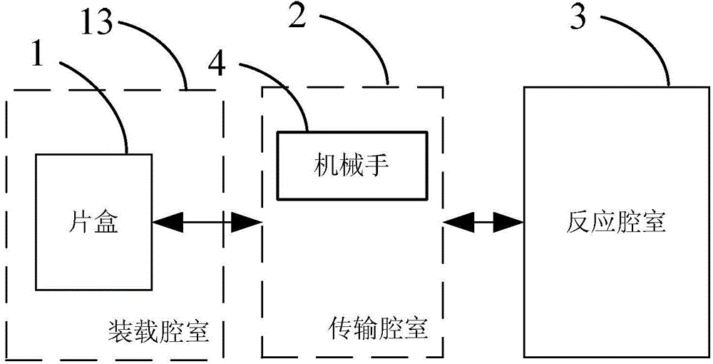
technical field [0001] The invention relates to the technical field of microelectronic processing, in particular to a chip box positioning device and semiconductor processing equipment. Background technique [0002] Removing wafers from cassettes is the first step in the automatic transfer process of many semiconductor processing equipment, so the efficiency and reliability of wafer removal has become one of the important prerequisites for highly automated wafer production. [0003] figure 1 Schematic block diagram of semiconductor processing equipment. Such as figure 1 As shown, the semiconductor processing equipment includes a loading chamber 13 , a transfer chamber 2 and a reaction chamber 3 . Wherein, the loading chamber 13 is used to carry the cassette 1 with a plurality of wafers placed therein; a manipulator 4 is arranged in the transfer chamber 2 for taking out or putting in the wafer 6 from the cassette 1 in the loading chamber 13, And moving the wafer 6 into or...

Claims


Application Information

Patent Timeline
IPC IPC(8): H01L21/673H01L21/68
Inventor 余志龙贾强李冬冬
Owner BEIJING NAURA MICROELECTRONICS EQUIP CO LTD
Learn More