Dimmable power switch

A power switch and dimming technology, applied in the direction of light source, electric light source, electric lamp circuit layout, etc., can solve the problems of low power measurement accuracy, thyristor flicker, accidental conduction, etc., to improve the low power measurement accuracy, improve The effect of reliability

Active Publication Date: 2016-02-17
LUCIS TECH SHANGHAI
View PDF3 Cites 3 Cited by
  • Summary
  • Abstract
  • Description
  • Claims
  • Application Information

AI Technical Summary

Problems solved by technology

[0003] The object of the present invention is to provide a dimmable power switch. This dimmable power switch solves the situation that the thyristor is subjected to an excessively high reverse electromotive force and is accidentally turned on when the current is switched when the power is large. It greatly improves the reliability of the application in high-power LED lamps; at the same time, it also solves the phenomenon of flicker caused by the unexpected shutdown of the thyristor due to the small power of the LED lamp and the discontinuous current, and improves the power consumption caused by the large difference in load power. The problem of low measurement accuracy

Method used


Image

  • Dimmable power switch
  • Dimmable power switch
  • Dimmable power switch

Examples


Embodiment

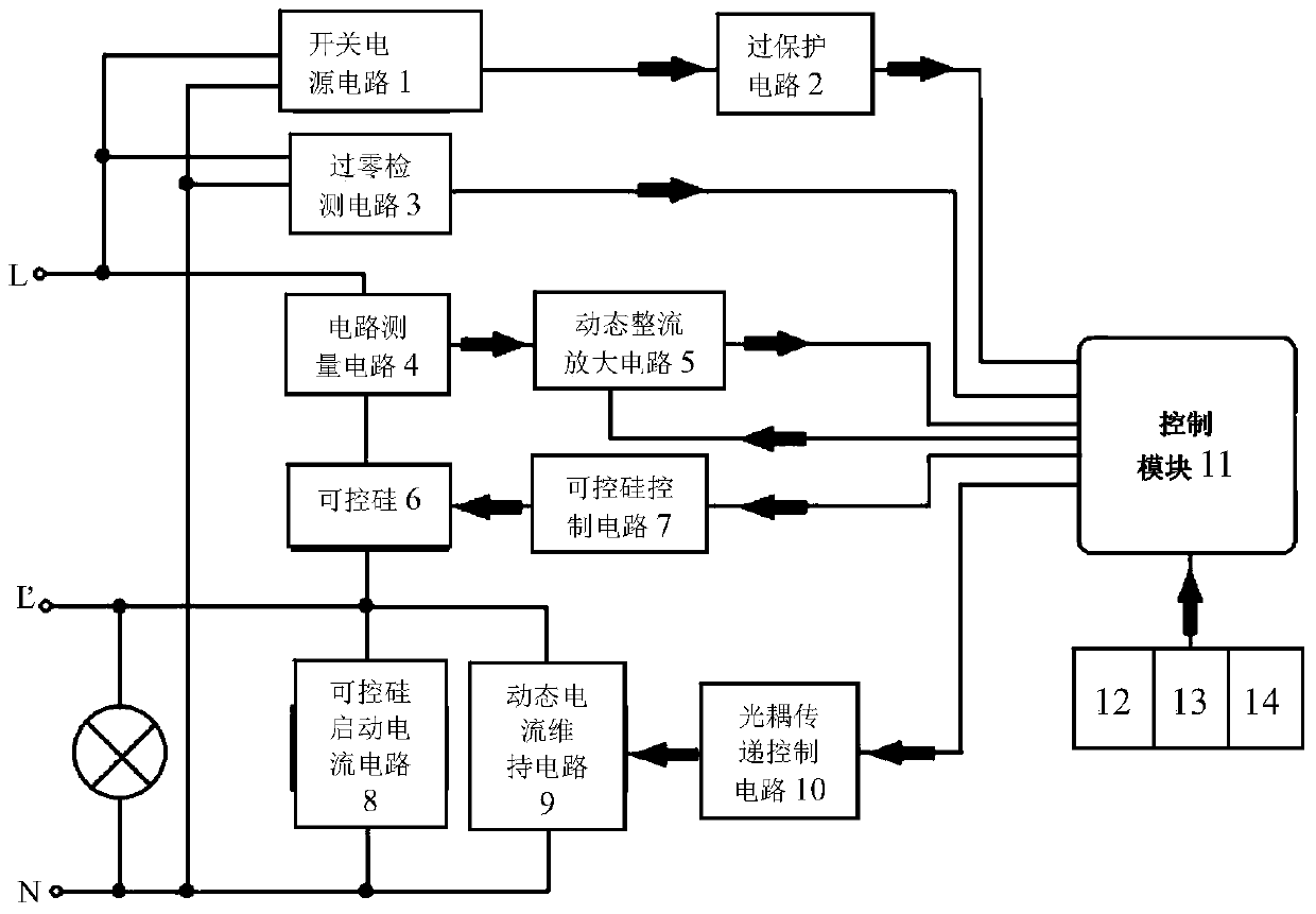
[0029] Embodiment: a dimmable power switch, including a zero wire terminal, an LED live wire terminal and a mains live wire terminal, the LED live wire terminal is used to connect an LED lamp, and the mains power live wire terminal is used to Connecting to the mains live wire, it also includes: a current detection circuit 4, a thyristor 6, a control module 11, a zero-crossing detection circuit 3, an on-off key 12 connected to the control module 11, a positive dimming key 13 and a negative dimming key 14;

[0030] The input end of the zero-crossing detection circuit 3 is connected to the live wire and the neutral wire of the mains, and the output end of the zero-crossing detection circuit is connected to the control module 11 for detecting zero point information in the alternating current of the mains, thereby generating an alternating current zero-crossing signal;

[0031] A current detection circuit 4 and a thyristor 6 are connected in series between the LED live wire terminal...


PUM


Abstract

The invention discloses a dimmable power switch, which comprises a current detection circuit, a thyristor, a control module and a zero cross detection circuit, wherein an input end of the zero cross detection circuit is connected to a fire line and a zero line of electric supply; the current detection circuit and the thyristor are connected between an LED fire line connection terminal and an electric supply fire line connection terminal in series; a zero line connection terminal and the LED fire line connection terminal are connected with a thyristor starting current circuit and a dynamic current maintaining circuit in parallel; the thyristor starting current circuit comprises a resistor and a capacitor, which are connected with each other in series; a dynamic rectifier-amplifier circuit is arranged between the current detection circuit and the control module; and the control module controls a thyristor control circuit to generate trigger pulse current according to an alternating current zero cross signal, and dynamically adjusts whether the dynamic current maintaining circuit is enabled or not according to a detection current signal from the current detection circuit. According to the dimmable power switch, the condition that the thyristor is unexpectedly closed due to bearing over-high counter electromotive force in a current switching process at relatively high power is avoided; and the flicker phenomenon that the thyristor is unexpectedly closed due to the fact that an LED lamp is relatively low in power and discontinuous in current is also avoided.

Description

technical field [0001] The invention relates to the technical field of power switches, in particular to a dimmable power switch. Background technique [0002] A switch is a component used to turn on and off a circuit. It is widely used to make the moving contact and the static contact turn on or off and realize the switching of the circuit. Due to the low power consumption and energy saving of LED lamps, the spectrum of LEDs is almost concentrated in the visible light frequency band, and the electro-optical power conversion is close to 100%. 60lm / W, the lifespan is less than 8000 hours, T5 fluorescent lamp is 96lm / W, the lifespan is about 10000 hours, and the white light LED with a diameter of 5mm can exceed 150lm / W, and the lifespan can be more than 100000 hours, which is widely used. LED light control switches have also developed from traditional buttons to touch switches. However, on the one hand, LED lamps cannot be well adapted to traditional thyristor dimmers, because...

Claims


Application Information

Patent Timeline
Patent Type & Authority Applications(China)
IPC IPC(8): H05B37/02
CPCY02B20/40
Inventor 关山赵涛曹福兵
Owner LUCIS TECH SHANGHAI
Why Eureka
Try Eureka