Tyre clamping device

A technology for tires and clips, which is applied in the direction of lifting devices, etc., can solve the problems of increased manufacturing costs, easy damage to the inner surface of tires, and large occupied area, so as to achieve the effects of improving efficiency, quick pick and place, and small occupied space

Active Publication Date: 2016-02-24
BLUESWORD INTELLIGENT TECH CO LTD
View PDF5 Cites 7 Cited by
  • Summary
  • Abstract
  • Description
  • Claims
  • Application Information

AI Technical Summary

Problems solved by technology

[0002] In tire production, it is necessary to grab the finished tires and transport them to the storage area through logistics equipment for storage. The existing tire clamping device is generally tensioned in the inner ring of the tire to fix the tire. This method is easy Injury to the inner surface of the tire
At the same time, the conventional tire clamp needs to be moved outward to facilitate the tire to enter before the tire enters. This structure occupies a large area and increases the manufacturing cost.

Method used


Image

  • Tyre clamping device
  • Tyre clamping device
  • Tyre clamping device

Examples


Embodiment Construction

[0026] Attached below figure 1 to attach Figure 6 The present invention will be further described.

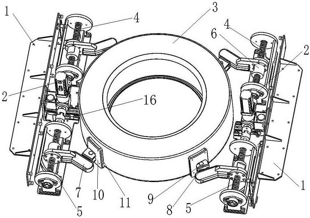
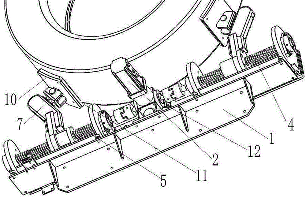
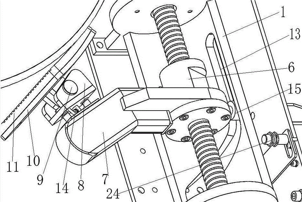
[0027] as attached figure 1 As shown, a tire clamping device includes: two bases 1, which are installed parallel to each other on the fork of a stacker or a shuttle, and each base 1 is equipped with two symmetrical clamping arms 7 along the length direction The clamp arm driving device is arranged on the base 1, and is used to drive the two clamp arms 7 on each base 1 to move synchronously and relatively in the opposite direction along the horizontal direction. When the clamp arm driving device drives the clamp arm 7 to move to the innermost end , the space between the four clamp arms 7 is less than the outer diameter of the tire 3, when the clamp arm driving device drives the clamp arm 7 to move to the outermost end, the space between the four clamp arms 7 is greater than the outer diameter of the tire 3; and The clamp arm guiding mechanism is arranged on the base 1, and i...


PUM


Abstract

The invention discloses a tyre clamping device. The tyre clamping device comprises two bases, a clamping arm drive device and a clamping arm guide mechanism, wherein two symmetrical clamping arms are installed on each base along a length direction; the clamping arm drive device drives the clamping arms to move inwards, and meanwhile, the four clamping arms are turned over downwards, and finally clamp tyres. The tyre clamping device can realize vertical stacking for a plurality of tyres, thus the transport efficiency is increased; then a stacker or a shuttle vehicle moves to the corresponding warehousing area, the tyres are in a clamped state and capable of being prevented from falloff during the transport process therefore, rapid pick-and-place for the tyres is realized, and sorting and stacking can be realized through pick-and-place, thus the efficiency is increased. Because the tyre clamping device is installed on a fork of the stacker or the shuttle vehicle, and the clamping arms turn over upwards while moving outwards, the occupied space is less.

Description

technical field [0001] The invention relates to a tire holding device. Background technique [0002] In tire production, it is necessary to grab the finished tires and transport them to the storage area through logistics equipment for storage. The existing tire clamping device is generally tensioned in the inner ring of the tire to fix the tire. This method is easy Injury to the inner surface of the tire. At the same time, conventional tire clamps need to move outwards before the tires enter to facilitate the tires to enter. This structure occupies a large area and increases the manufacturing cost. Contents of the invention [0003] In order to overcome the deficiencies of the above technologies, the present invention provides a tire holding device that can clamp the outer wall of the tire while occupying a small space. [0004] The technical scheme that the present invention overcomes its technical problem adopts is: [0005] A tire holding device, comprising: [0006...

Claims


Application Information

Patent Timeline
Patent Type & Authority Applications(China)
IPC IPC(8): B66F9/18B66F9/24
Inventor 吴耀华张小艺张贻弓蒋霞
Owner BLUESWORD INTELLIGENT TECH CO LTD
Why Eureka
Try Eureka