Blade lock with radial displacement being mutually controlled through front locking mechanism and rear locking mechanism

A locking mechanism and radial displacement technology, applied in the field of locks, can solve the problems of inability to release the locking body of the lock body, unable to prevent technical unlocking or violent unlocking, etc., and achieve the effects of increasing the difficulty of unlocking, simple structure and low cost

Active Publication Date: 2016-02-24
厦门天工创新科技发展有限公司
View PDF8 Cites 0 Cited by
  • Summary
  • Abstract
  • Description
  • Claims
  • Application Information

AI Technical Summary

Problems solved by technology

If one or more of the key teeth on the key do not match the combination of the blades, the grooves on the blades in the lock cylinder will not match the bottom of the tumbler, and the tumbler will not be able to fall, and the tumbler will not be released. The clamping of the lock head body, in this way, the lock cylinder and the lock head body are connected through the tumbler, and the lock cylinder cannot rotate
Although this blade lock of the prior art has better security than the pin lock, it still cannot prevent technical unlocking or violent unlocking.

Method used


Image

  • Blade lock with radial displacement being mutually controlled through front locking mechanism and rear locking mechanism
  • Blade lock with radial displacement being mutually controlled through front locking mechanism and rear locking mechanism
  • Blade lock with radial displacement being mutually controlled through front locking mechanism and rear locking mechanism

Examples


Embodiment 1

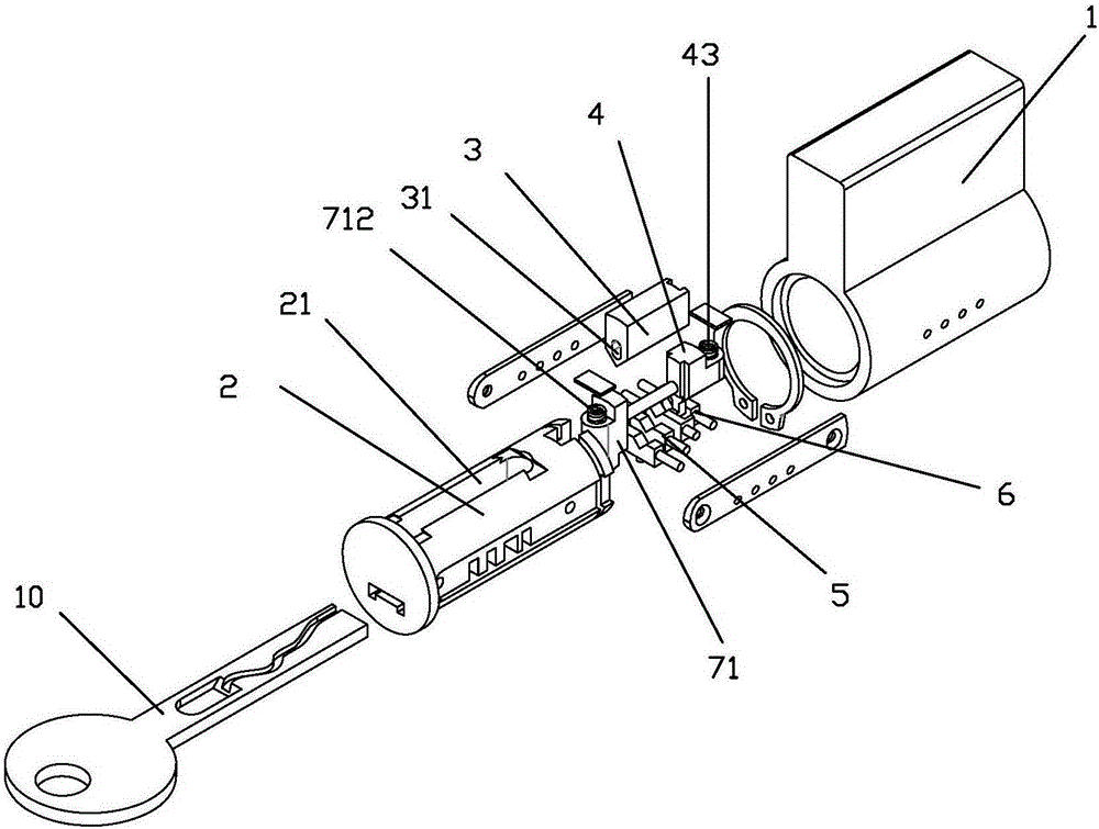
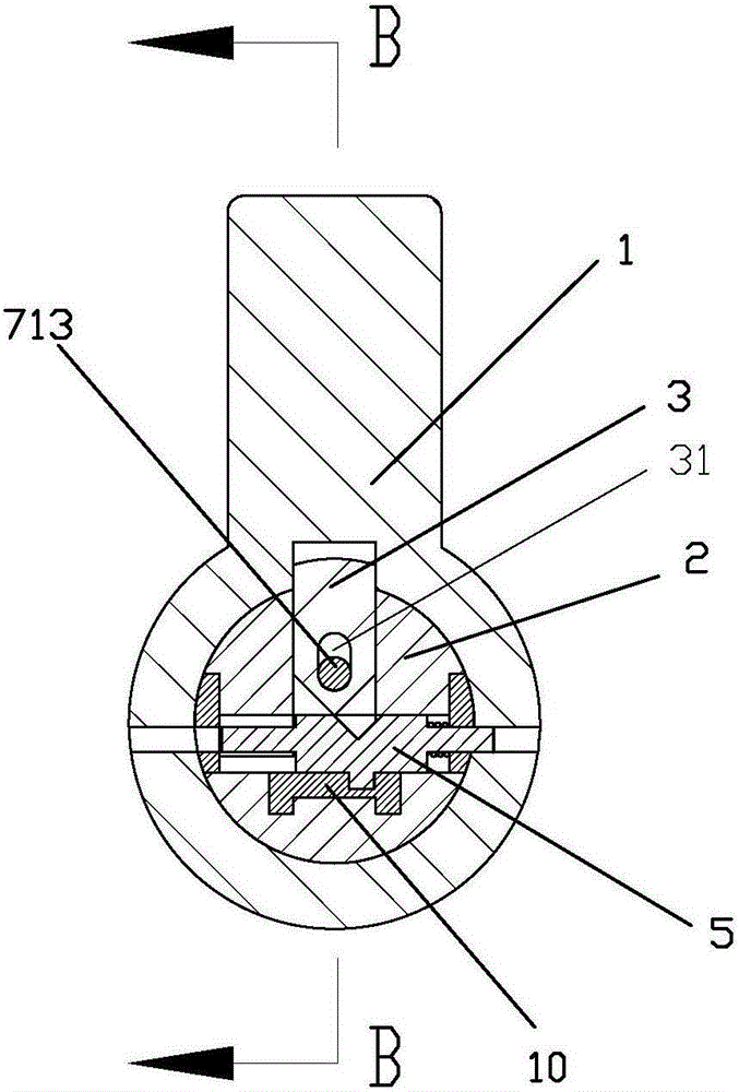
[0064] see Figure 1 to Figure 13 As shown, a front and rear locking mechanism mutual control radial displacement blade lock of the present invention includes a lock head and a key 10; the lock head includes a lock head body 1, a lock cylinder 2, a front tumbler 3, and a rear tumbler 4 , the front blade mechanism 5 and the rear blade mechanism 6, wherein the front blade mechanism 5 has a plurality of blades 51, and the rear blade mechanism 6 has a blade 61; the lock core 2 is rotatably contained in the lock head body 1; the front tumbler 3 Set side by side with the rear tumbler 4 between the lock body 1 and the lock cylinder 2, the lock body 1 and the lock cylinder 2 are respectively provided with tumblers for accommodating the lock body of the front tumbler 3 and the rear tumbler 4 Groove 11, the tumbler groove 21 of the lock cylinder; the front blade mechanism 5 and the rear blade mechanism 6 are installed in the lock cylinder 2 respectively and cooperate with the front tumb...

Embodiment 2

[0089] see Figure 14 to Figure 26 As shown, a front and rear locking mechanism mutual control radial displacement blade lock of the present invention includes a lock head and a key 10; the lock head includes a lock head body 1, a lock cylinder 2, a front tumbler 3, and a rear tumbler 4 , the front blade mechanism 5 and the rear blade mechanism 6, wherein the front blade mechanism 5 has a plurality of blades 51, and the rear blade mechanism 6 also has a plurality of blades 61; the lock core 2 is rotatably contained in the lock head body 1; the front tumbler 3 and the rear tumbler 4 are arranged side by side between the lock head body 1 and the lock cylinder 2, and the lock head body 1 and the lock cylinder 2 are respectively provided with lock body locks for accommodating the front tumbler 3 and the rear tumbler 4. The bolt groove 11, the bolt groove 21 of the lock core; the front blade mechanism 5 and the rear blade mechanism 6 are respectively installed in the lock core 2 an...

Embodiment 3

[0109] see Figure 27 As shown, a front and rear locking mechanism mutual control radial displacement blade lock of the present invention is different from Embodiment 2 in that the delayer 94 is another form, and the delayer 94 includes a push rod 961, transition piece 962, fixed seat 963 and compression spring 964, described ejector rod 961, transition piece 962 and compression spring 964 are installed in the cavity of fixed seat 963 slidingly, and the first boss 9611 of ejector rod is slidably installed in fixed seat sliding In the rail 9631, the rear end of the compression spring 964 is stretched on the inner wall of the rear end of the fixed seat 963, the front end of the compression spring 964 is stretched at the end of the inner hole at the rear end of the transition block 962, and the front end of the transition block 962 is movably installed at the end of the inner hole at the rear end of the push rod 961 , the second boss 9621 of the transition block also cooperates w...


PUM


Abstract

The invention discloses a blade lock with the radial displacement being mutually controlled through a front locking mechanism and a rear locking mechanism. The blade lock comprises a lock body, a lock cylinder, a front brake bolt, a rear brake bolt, a front blade mechanism, a rear blade mechanism, a lock gate and a key. The front brake bolt and the rear brake bolt are arranged side by side between the lock body and the lock cylinder and matched with the front blade mechanism and the rear blade mechanism which are installed inside the lock cylinder to form the front locking mechanism and the rear locking mechanism respectively. The front locking mechanism controls the rear locking mechanism to rotate. The rear locking mechanism controls decoding conditions of the front locking mechanism through a control mechanism. Before the rear brake bolt moves in place, the front locking mechanism does not have the decoding conditions. After the rear locking mechanism is decoded, a spring pushes the rear brake bolt to move downwards in place in the radial direction, the lock gate is closed at the time, control over the front locking mechanism is released by the control mechanism so that the key can decode the front locking mechanism, and unlocking is achieved by rotating the lock cylinder. According to the blade lock, the novel idea and method for replacing time difference with potential difference is adopted, and at present, the blade lock is one of the most effective locks for preventing technological unlocking and violent unlocking in the world.

Description

technical field [0001] The invention relates to a lock, in particular to a radial displacement blade lock with mutual control of front and rear locking mechanisms. Background technique [0002] The blade lock is a kind of lock. The blade lock usually includes a lock body, a lock cylinder, a tumbler, a leaf and a key. The tumbler is arranged between the lock body and the lock cylinder, usually between the lock body and the lock cylinder. With a tumbler slot, the tumbler can only move at the tumbler slot of the lock head body and the tumbler slot of the lock cylinder. When it is not unlocked, the tumbler is at the tumbler slot of the lock head body and the lock cylinder. , so that the lock core can not rotate relative to the lock head body, when unlocking, the tumbler falls, and the lock core at this time can rotate relative to the lock head body to realize unblanking. This kind of blade lock usually has a groove on the upper part of the blade. Through the matching of the key...

Claims


Application Information

Patent Timeline
Patent Type & Authority Applications(China)
IPC IPC(8): E05B29/00E05B15/14E05B15/00
Inventor 朱嘉斌
Owner 厦门天工创新科技发展有限公司
Why Eureka
Try Eureka