Self-centering rotary detection table

A technology of rotation detection and self-centering, which is applied in the direction of measuring devices and instruments, can solve the problems of tolerance in the inner hole of the wheel, inflexible rotation of the wheel body, and difficulty in concentricity inspection, so as to achieve short production period, improve inspection efficiency and The effect of accuracy and ease of procurement

Inactive Publication Date: 2016-02-24
DALIAN SHENGLONG MACHINERY
View PDF6 Cites 3 Cited by
  • Summary
  • Abstract
  • Description
  • Claims
  • Application Information

AI Technical Summary

Problems solved by technology

There are tolerances in the machining of the inner hole of the wheel. It is impossible for all the inner holes of the machined wheel to have the same size, so it is difficult to perfectly match the mandrel.
If the inner hole of the wheel is larger than the mandrel, although the wheel body can rotate flexibly, there will be a gap between the mandrel and the wheel body, which will cause errors during inspection
If the inner hole of the wheel is smaller than or equal to the mandrel, the wheel body may not be able to be put into the mandrel. Even if it can be put in, it will cause the wheel body to rotate inflexibly, or even cannot rotate, making it difficult to check the concentricity and reduce the inspection efficiency. Moreover, each wheel body of different sizes must be equipped with a mandrel, which is very troublesome to make

Method used


Image

  • Self-centering rotary detection table
  • Self-centering rotary detection table
  • Self-centering rotary detection table

Examples


Embodiment 1

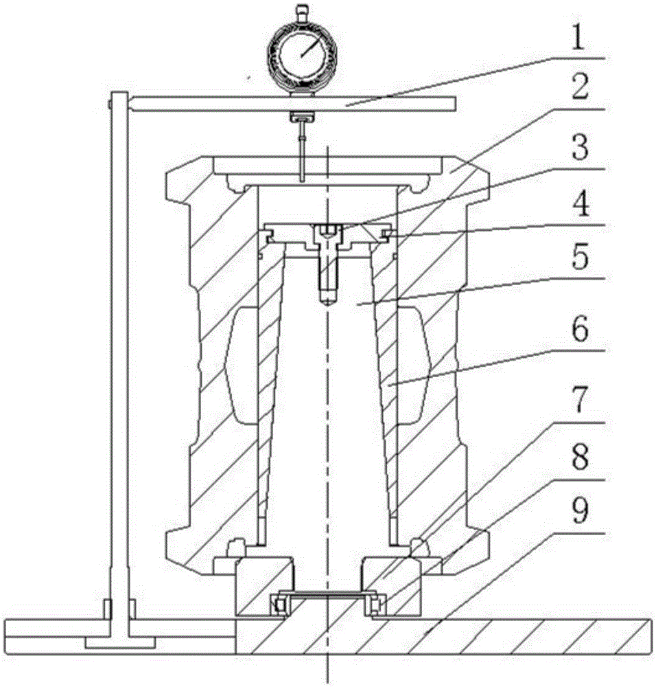
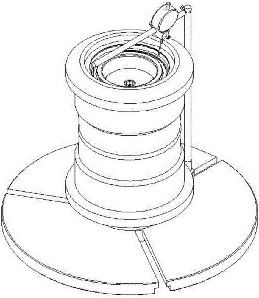
[0021] Such as figure 2 , image 3 As shown, the self-centering rotary detection platform includes a table frame 1, an expansion and opening gland 4, a tensioning column 5, an expansion jacket 6 and a chassis 9; Flexible rotation, preferably, the middle part of chassis 9 is installed with tensioning column 5 through positioning ring 7, bearing 8 rotation, bearing 8 is installed on the chassis 9, positioning ring 7 is sleeved on bearing 8, and the bottom of tensioning column 5 is installed on Inside the positioning ring 7. The tensioning column 5 is a conical structure, and the tensioning column 5 is covered with a tensioning jacket 6, and the tensioning jacket 6 is a hollow cylindrical structure, and the cavity is conical and matches the shape of the tensioning column 5 , the top of the expansion jacket 6 is equipped with an expansion gland 4, the expansion gland 4 is threaded with the expansion column 5 through the tightening screw 3, the expansion gland 4 has two function...

Embodiment 2

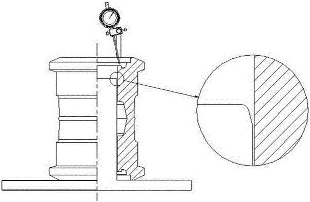
[0023] Different from Embodiment 1, such as Figure 4 , Figure 5 As shown in the figure, a meter head is installed on the vertical bar, which is used to detect the concentricity of the tread of the welded part of the double-sided roller body.


PUM


Abstract

The invention discloses a self-centering rotary detection table which comprises a gauge stand, an opening gland, a tensioning column, a tensioning cover and a chassis, wherein the tensioning column is rotationally arranged in the middle of the chassis and has a conical structure; the tensioning cover is arranged outside the tensioning column in a sleeving manner and has a cylindrical cavity structure; the cavity is conical and is matched with the appearance of the tensioning column; the opening gland is arranged on the top of the tensioning cover and is in threaded connection with the tensioning column by virtue of a tightening screw; the gauge stand is arranged on the chassis in a sliding manner; and a gauge head is arranged on the gauge stand. The self-centering rotary detection table disclosed by the invention is flexible to use, and the detection efficiency and accuracy of each location degree of the wheel are greatly improved; the detection table is convenient to manufacture, low in cost and high in utilization rate and can be matched with multiple common check measuring tools; and complicated detection is simplified, multiple sizes and form and location tolerances needing to be detected in a rotating state are unified together, one-time detection is realized, and the result is obtained.

Description

technical field [0001] The invention relates to the technical field of testing equipment, in particular to a self-centering rotating testing platform. Background technique [0002] In the construction machinery industry, supporting rollers and supporting rollers are required for the traveling mechanisms of excavators, bulldozers, drilling machines, crawler cranes and other equipment. The liquid pressurized oil is sealed inside the rollers and supporting rollers, which are vulnerable parts. Track rollers and supporting wheels are limited by the service life of the seals, and the general warranty period is one year or 2000 hours of work. There are generally more than a dozen parts that make up the rollers and the supporting wheels, the most important parts of which are the wheel body, the shaft and the end cover, and they are also called the three major parts of the supporting wheel. [0003] Among the three major parts, the wheel body has the most processing procedures, and...

Claims


Application Information

Patent Timeline
Patent Type & Authority Applications(China)
IPC IPC(8): G01B21/00G01B21/24
CPCG01B21/00G01B21/24
Inventor 李沫杨兴道曲永哲
Owner DALIAN SHENGLONG MACHINERY
Why Eureka
Try Eureka