
Component mounting device

A technology for installing devices and components, applied in the direction of electrical components, electrical components, etc., can solve the problems of large weight and cost increase of component installation devices

Active Publication Date: 2016-02-24
FUJI KK
View PDF5 Cites 2 Cited by
  • Summary
  • Abstract
  • Description
  • Claims
  • Application Information

AI Technical Summary

Problems solved by technology

However, in the conventional component mounting apparatus of this type, since the entire mounting head including the R-axis driving device that rotates the turret head and the θ-axis driving device that rotates the suction nozzle is replaced, the replacement head part It becomes large and heavy, and the cost of the component mounting device increases

Method used


Image

  • Component mounting device
  • Component mounting device
  • Component mounting device

Examples


Embodiment Construction

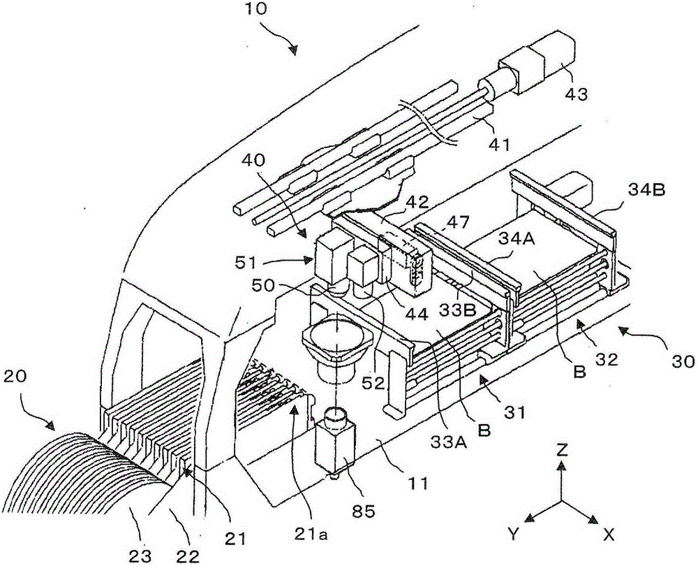
[0029] Embodiments of the present invention will be described below based on the drawings. like figure 1 As shown, the component mounting device 10 includes a component supply device 20 , a board transfer device 30 , and a component transfer device 40 .

[0030] As an example, the components supply apparatus 20 is configured so that a plurality of tape feeders 21 are arranged side by side in the X-axis direction on the base 11 . The tape feeder 21 is detachably attached to the main body frame 22 detachably attached to the base 11, and has a structure in which a plurality of electronic components (hereinafter referred to as components) are wound and accommodated at intervals. The tape formed in one row is supplied to the tape reel 23 . Inside the tape feeder 21, although not shown in the figure, there is built-in a motor which becomes the driving source of the pitch conveyor belt, and the motor is used to send the tape one pitch at a time, and the components accommodated in t...


PUM


Abstract

Provided is a component mounting device that, if components are adsorbed by four adsorption nozzles in a circle, allows all components larger than a prescribed size to be imaged at once by changing the positions of components to be image-processed without increasing the field of view of a component camera. A rotary head (50) comprises at least two types of rotary heads, a first rotary head (50A) by which four adsorption nozzles (54) are each rotatably held in a circle and a second rotary head (50B) by which more than four adsorption nozzles are each rotatably held on the diameter of a circle of the same pitch as the adsorption nozzles of the first rotary head. The first rotary head is attached to a drive unit (51). A control device (90) is provided that, if the components held by the adsorption nozzles are imaged by a component camera (85), controls the angular position of the first rotary head and the angular positions of the components adsorbed to the adsorption nozzles so that each angular position is changed in 45 degree intervals.

Description

technical field [0001] The present invention relates to a component mounting device including a rotary head holding a plurality of suction nozzles on the circumference. Background technique [0002] As the suction nozzle held by the mounting head of the component mounting device, an appropriate suction nozzle according to the type (size, shape, etc.) of the component to be sucked is used. Therefore, it is described in Patent Document 1, for example, that the suction nozzle of the mounting head can be replaced according to the type of the component to be sucked. However, in the conventional component mounting apparatus of this type, since the entire mounting head including the R-axis driving device that rotates the turret head and the θ-axis driving device that rotates the suction nozzle is replaced, the replacement head part It becomes large and heavy, and the cost of the component mounting device increases. [0003] Patent Document 1: Japanese Patent Laid-Open No. 2009-17...

Claims


Application Information

Patent Timeline
Patent Type & Authority Applications(China)
IPC IPC(8): H05K13/04
CPCH05K13/041H05K13/0812H05K13/0404
Inventor 西山识
Owner FUJI KK
Features
  • Generate Ideas
  • Intellectual Property
  • Life Sciences
  • Materials
  • Tech Scout
  • Unparalleled Data Quality
  • Higher Quality Content
  • 60% Fewer Hallucinations
Learn More