Electric balance car

An electric balance car and pedal technology, applied in the electromechanical field, can solve problems such as easily damaged axles, damage to load-bearing base components, safety issues, etc., and achieve the effects of improving comfort, protecting axles, components and personal safety

Active Publication Date: 2016-03-02
SHENZHEN KIXIN ELECTRONICS CO LTD
View PDF8 Cites 4 Cited by
  • Summary
  • Abstract
  • Description
  • Claims
  • Application Information

AI Technical Summary

Problems solved by technology

Since the load-bearing base is directly fixed to the wheel shaft of the wheel hub motor, the load-bearing force generated by the user after stepping on the pedal assembly is directly and rigidly transmitted to the wheel shaft of the wheel hub motor, causing discomfort to the user and easily causing damage to the wheel shaft of the wheel hub motor. The rigid impact force is easy to damage the wheel shaft; in addition, because the wheel shaft of the hub motor is in the cente

Method used


Image

  • Electric balance car
  • Electric balance car
  • Electric balance car

Examples


Embodiment 1

[0039] This embodiment provides an electric balancing car, which is mainly a two-wheel electric self-balancing twisting car.

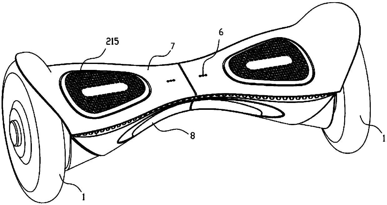
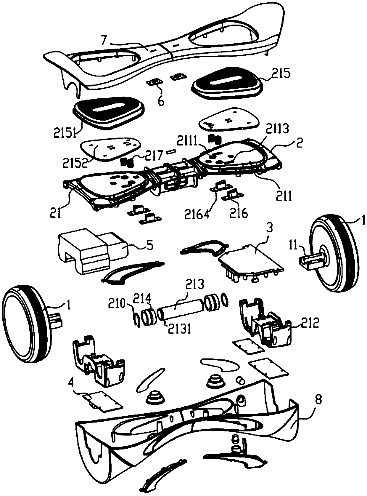
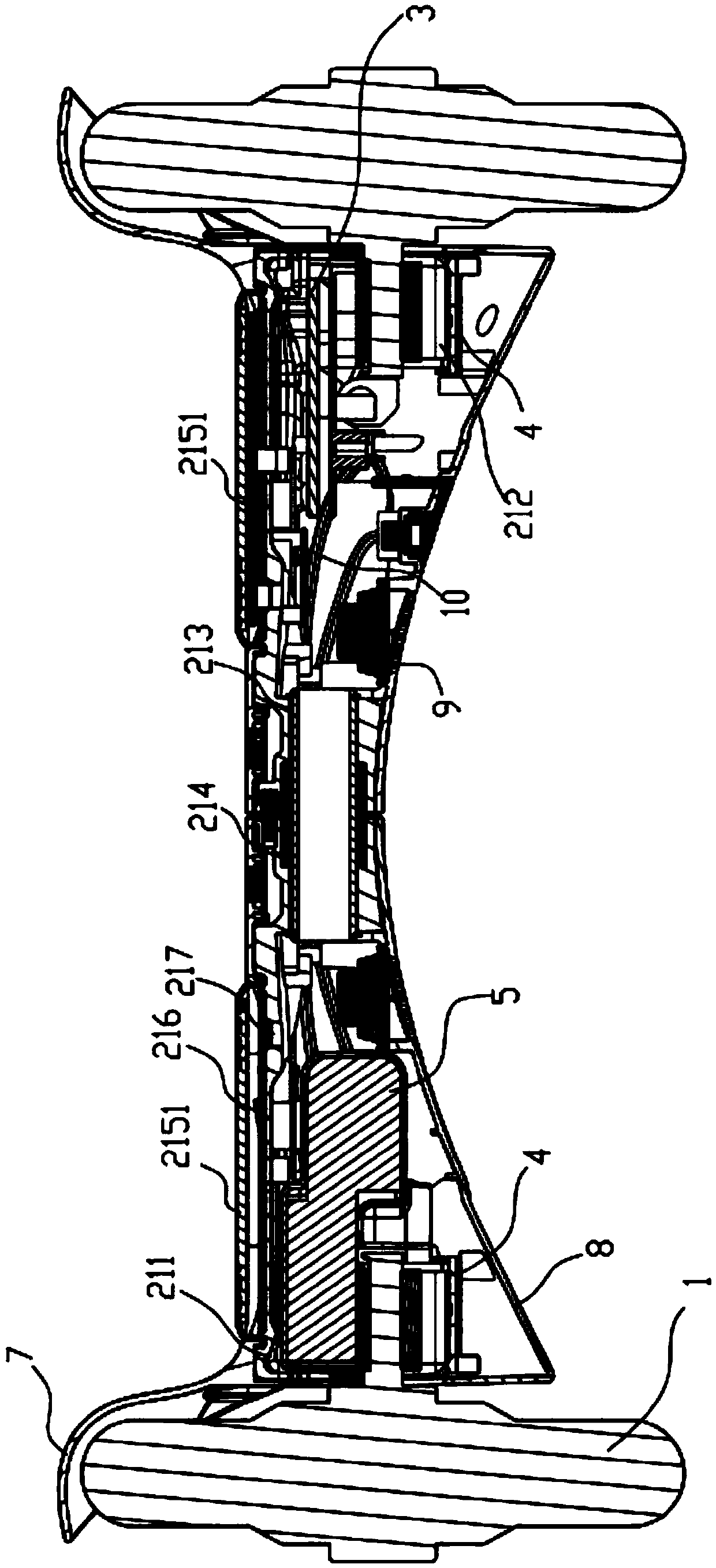
[0040] like Figure 1-3As shown, the electric balance car mainly includes: a wheel assembly 1 with a wheel shaft 11 and a pedal system 2 . The wheel assembly 1 is a hub motor. The pedal system 2 includes: two pedal assemblies 21 , and each pedal assembly 21 is correspondingly assembled with one wheel assembly 1 . The pedal assembly 21 includes: a load-bearing base 211 and a suspension frame 212 . Among them, such as Figure 4-5 As shown, the suspension frame 212 includes: a support portion 2121 abutted against and fixed to the wheel shaft 11, a force receiving portion 2122 assembled with the load-bearing base 211 and separately arranged on both sides of the axial projection line of the wheel shaft 11 on the load-bearing base 211, And, the connecting portion 2123 located between the supporting portion 2121 and the force receiving portion 2122 . The...

Embodiment 2

[0054] The difference between this embodiment and the foregoing embodiments mainly lies in: the structure of the suspension frame 212 is different. That is to say, in this embodiment: from the load-bearing base 211 to the suspension frame 212, the cross section of the combination part 2100 of the force receiving part 2122 and the connecting part 2123 along the radial direction of the wheel shaft 11 is arc-shaped, and the support part 2121 is along the radial direction of the wheel shaft 11. The cross-section is annular, and the outer surface of the support part 2121 is in contact with the inner surface of the combination part 2100, as Figure 12 shown. or, as in Figure 13 As shown, the outer surface of the support part 2121 is in contact with the outer surface of the combination part 2100, and the suspension frame 212 includes: a fifth force receiving part and a sixth force receiving part assembled with the load-bearing base 211 and arranged on one side of the projection lin...

Embodiment 3

[0056] The difference between this embodiment and the above-mentioned embodiments mainly lies in: the setting position of the micro switch 216 is different. That is to say, in this embodiment: the switch base 2161 is fixed on the footrest 215 , the fixed part of the action reed 2162 is fixed to the footrest 215 , and the free part can abut against the load-bearing base 211 .


PUM


Abstract

The invention discloses an electric balance car comprising a wheel assembly with a wheel shaft and a pedal system; the pedal system comprises two pedal assemblies; the pedal assembly comprises a bearing matrix and a hanger bracket; the hanger bracket comprises a support portion jointing and fixed with the wheel shaft, a bearing portion assembled with the bearing matrix and arranged on two sides of an axial projection line of the wheel shaft on the bearing matrix, and a connecting portion between the support portion and the bearing portion; the bearing portion receives the bearing force transferred by the bearing matrix; a preset distance is arranged between a bearing surface and the wheel shaft; when a user step on the pedal assembly, the bearing force can pass the bearing matrix and the hanger bracket in sequence, and is transferred on the wheel shaft; the preset distance is arranged between the bearing surface and the wheel shaft, the hanger bracket can generate damping effect so as to improve user comfortability, and thus protecting the wheel shaft; in addition, the electric balance car can protect parts and human body safety.

Description

technical field [0001] The present application relates to the electromechanical field, in particular to an electric balance car. Background technique [0002] Electric balance cars, also known as somatosensory cars, thinking cars, camera cars, etc., currently on the market mainly have two types of single-wheel and double-wheel. "Basic principle, use the gyroscope and acceleration sensor inside the car body to detect the change of the car body attitude, and use the servo control system to accurately drive the motor to make corresponding adjustments to maintain the balance of the system. [0003] Usually, a two-wheel electric balance car mainly includes a series of components such as two hub motors with wheel shafts and a pedal system located between the two hub motors. The pedal system includes two pedal assemblies. The pedal assembly includes a load-bearing base and a pedal. The load-bearing base is directly sleeved on the wheel shaft of the hub motor and fixed therewith. ...

Claims


Application Information

Patent Timeline
IPC IPC(8): B62K3/00B62J25/00
CPCB62K3/00B62K11/007B62J25/04
Inventor 何武
Owner SHENZHEN KIXIN ELECTRONICS CO LTD
Why Eureka
Try Eureka