Emulsion pump with closure between pressing head and locking cover improved

A lotion pump and lock cover technology, which is applied in the field of lotion pumps, can solve the problems of poor self-locking performance between the liquid inlet channel and the lock cover, and easy misoperation.

Active Publication Date: 2016-03-02
联昌喷雾泵(苏州)有限公司
View PDF4 Cites 5 Cited by
  • Summary
  • Abstract
  • Description
  • Claims
  • Application Information

AI Technical Summary

Problems solved by technology

The problem is: the self-locking performance of the liquid inlet channe

Method used


Image

  • Emulsion pump with closure between pressing head and locking cover improved
  • Emulsion pump with closure between pressing head and locking cover improved
  • Emulsion pump with closure between pressing head and locking cover improved

Examples


Embodiment 1

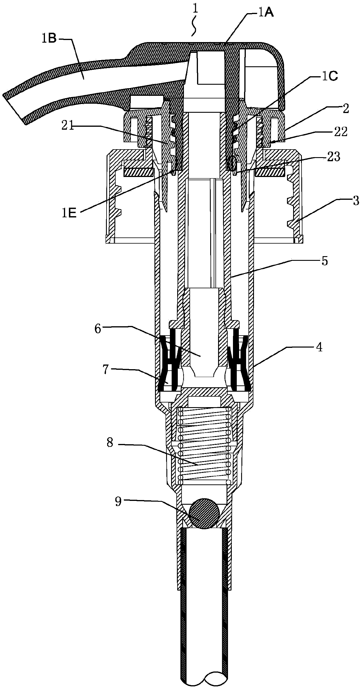
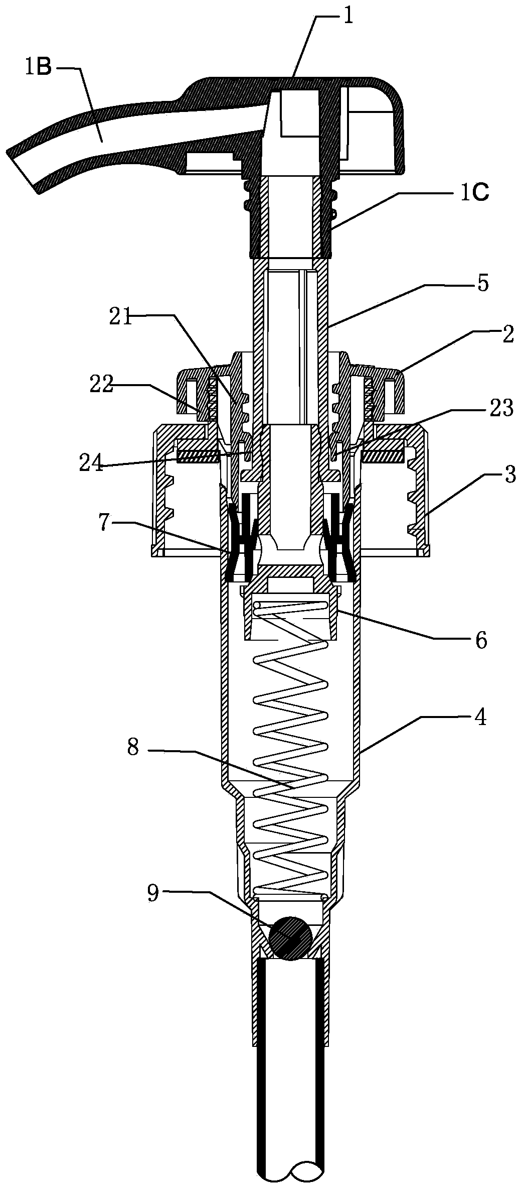
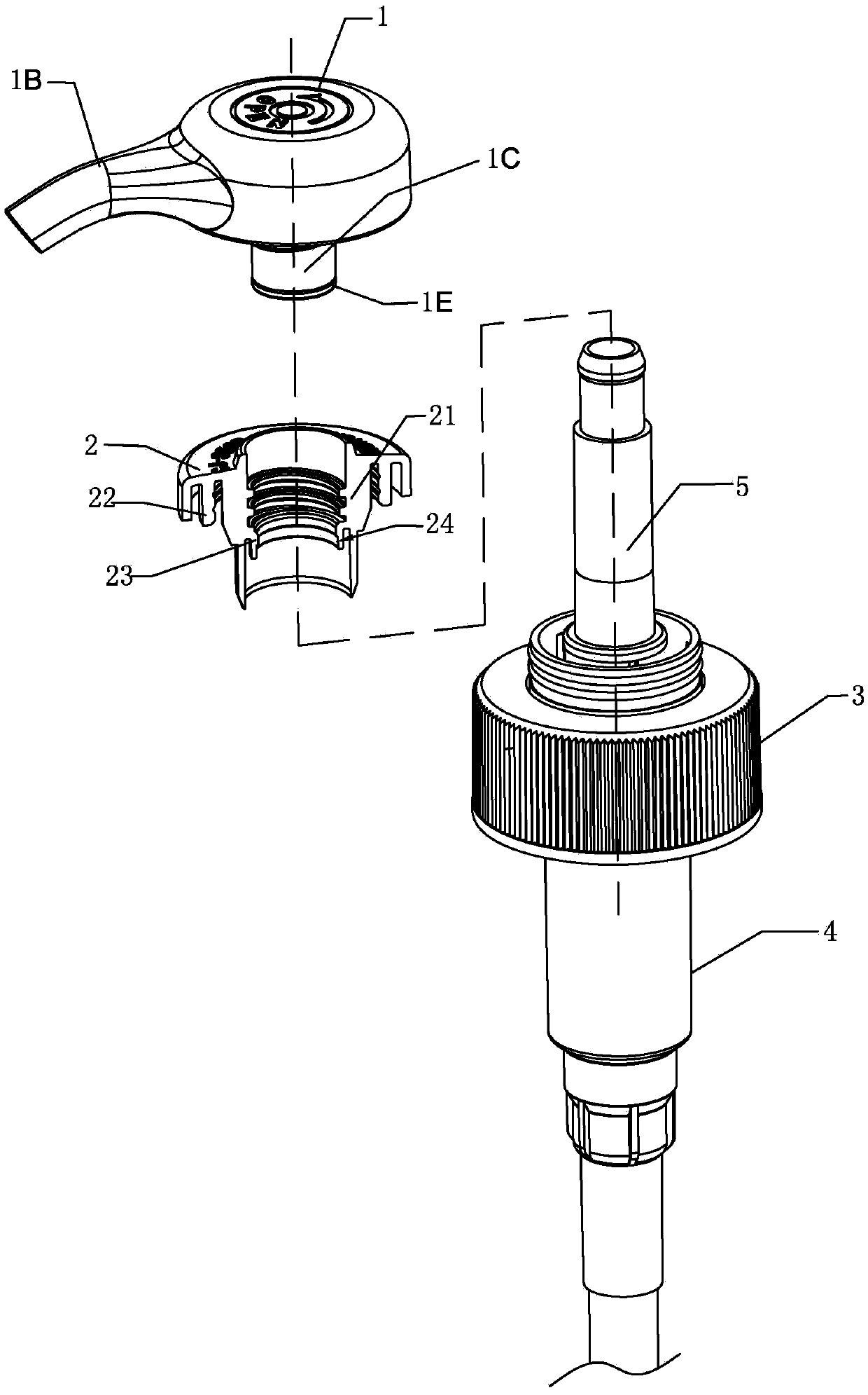
[0029] Such as figure 1 , figure 2 As shown, a lotion pump with an improved locking head and lock cover, including a press head 1, a lock cover 2, a thread 3, a body 4, a main post 5, an auxiliary post 6, a piston 7, a spring 8 and a glass ball 9 The press head 1 includes a base 1A, a liquid outlet nozzle 1B and a liquid inlet channel 1C, and the liquid inlet channel 1C communicates with the liquid outlet nozzle 1B; the lock cover 2 includes a guide sleeve 21 at the center and an internal thread interface 22 surrounding the guide sleeve; The upper end of the body 4 passes through the thread 5 and is screwed to the internal thread interface of the lock cover 2 , the liquid inlet channel 1C of the press head 1 is connected to the upper end of the main column 5 , and the press head 1 is detachably connected with the lock cover 2 .

[0030] The press head 1 is provided with a locking device;

[0031] The guide sleeve 21 of the lock cover 2 has a single-head internal thread, and...

Embodiment 2

[0041] Such as Figure 4 As shown, there are several axial grooves 1F located on the lower part of the single-head external thread on the liquid inlet channel 1C; the axial grooves 1F have radial openings and lower end openings;

[0042] The guide sleeve 21 of the lock cover 2 has several teeth 25 located at the lower part of the single thread;

[0043] The teeth 25 cooperate with the axial groove 1F. When the push head rotates relative to the lock cover, the tooth 25 is in sliding fit with the axial groove 1F.

[0044] As a further improvement: the lower end of the guide sleeve of the lock cover is provided with a cylindrical seat 26 , and the teeth 25 are arranged on the inner wall of the cylindrical seat 26 .

Embodiment 3

[0046] Such as Figure 5 , Figure 6 As shown, the locking device includes a cylindrical interface 1D surrounding the liquid inlet channel 1C and a single-head thread arranged on the cylindrical interface;

[0047] The lower end of the cylindrical interface 1D is provided with an axial groove 1F, and the lower end of the guide sleeve 21 is provided with several teeth 25;

[0048] The single-start thread of the cylindrical interface 1D is screwed with the single-start thread on the guide sleeve 21, and the teeth 25 cooperate with the axial groove 1F.


PUM


Abstract

An emulsion pump with closure between a pressing head and a locking cover improved comprises the pressing head, the locking cover, a screw thread, a body, a main column, an auxiliary column, a piston, a spring and a glass ball. The pressing head comprises a base, an emulsion outlet nozzle and an emulsion inlet channel, and the emulsion inlet channel is communicated with the emulsion outlet nozzle; the locking cover comprises a guiding sleeve in the center and an internal-thread nipple surrounding the guiding sleeve; the upper end of the body penetrate through the screw thread to be in screw fit with the internal-thread nipple of the locking cover; the emulsion inlet channel of the pressing head is communicated with the upper end of the main column, the pressing head is detachably connected with the locking cover, and a locking device is arranged on the pressing head; and a one-head internal thread is arranged on the guiding sleeve of the locking cover, and the locking device is in screw fit with the guiding sleeve. By means of the structure, a one-head external thread of the emulsion inlet channel is in screw fit with the one-head internal thread of the guiding sleeve of the locking cover. Thus, the self locking performance is enhanced, the unlocking distance is increased, the emulsion pump is prevented from being opened at will, and the safety is enhanced.

Description

technical field [0001] The invention relates to a lotion pump. Background technique [0002] In the current prior art, there is a lotion pump that improves the locking of the press head and the lock cover, including the press head, the lock cover, the thread, the body, the main column, the auxiliary column, the piston, the spring and the glass ball, and the press head includes the base, The liquid outlet nozzle, the liquid inlet channel and the liquid guide channel connected to the liquid inlet channel and the liquid outlet nozzle; the lock cover includes a guide sleeve in the center and an internal thread interface surrounding the guide sleeve; the upper end of the body passes through the thread and the inner thread of the lock cover The threaded interface is screwed together, the liquid inlet channel of the press head is fixedly connected with the upper end of the main column, and the double thread of the liquid inlet channel is screwed with the thread on the guide sleeve ...

Claims


Application Information

Patent Timeline
IPC IPC(8): B65D47/34
Inventor 林添大
Owner 联昌喷雾泵(苏州)有限公司
Why Eureka
Try Eureka