Clamping device and slicer with same

A technology of clamping device and slicer, which is applied in the direction of measuring devices, sampling devices, clamps, etc., can solve problems such as wear and loss of clamping functions, and achieve the effects of reducing contact area, prolonging service life, and improving self-locking performance

Active Publication Date: 2018-11-13
LEICA MICROSYST LTD SHANGHAI SHANGHAI
View PDF9 Cites 5 Cited by
  • Summary
  • Abstract
  • Description
  • Claims
  • Application Information

AI Technical Summary

Problems solved by technology

And the user needs to clamp up to a hundred times a day, so it is quite hard work for the user
In addition, there will be wear between the eccentric bolt and the part used for clamping that is in contact with the eccentric bolt, and after a certain time, when the wear reaches a certain level, the system will lose its clamping function

Method used


Image

  • Clamping device and slicer with same
  • Clamping device and slicer with same
  • Clamping device and slicer with same

Examples


Embodiment Construction

[0095] Preferred embodiments of the present disclosure will be described below with reference to the drawings. It should be noted that the terms "upper", "lower", "left", "right", "front", "rear" and similar expressions used herein are for the purpose of illustration only and not to limit the present disclosure.

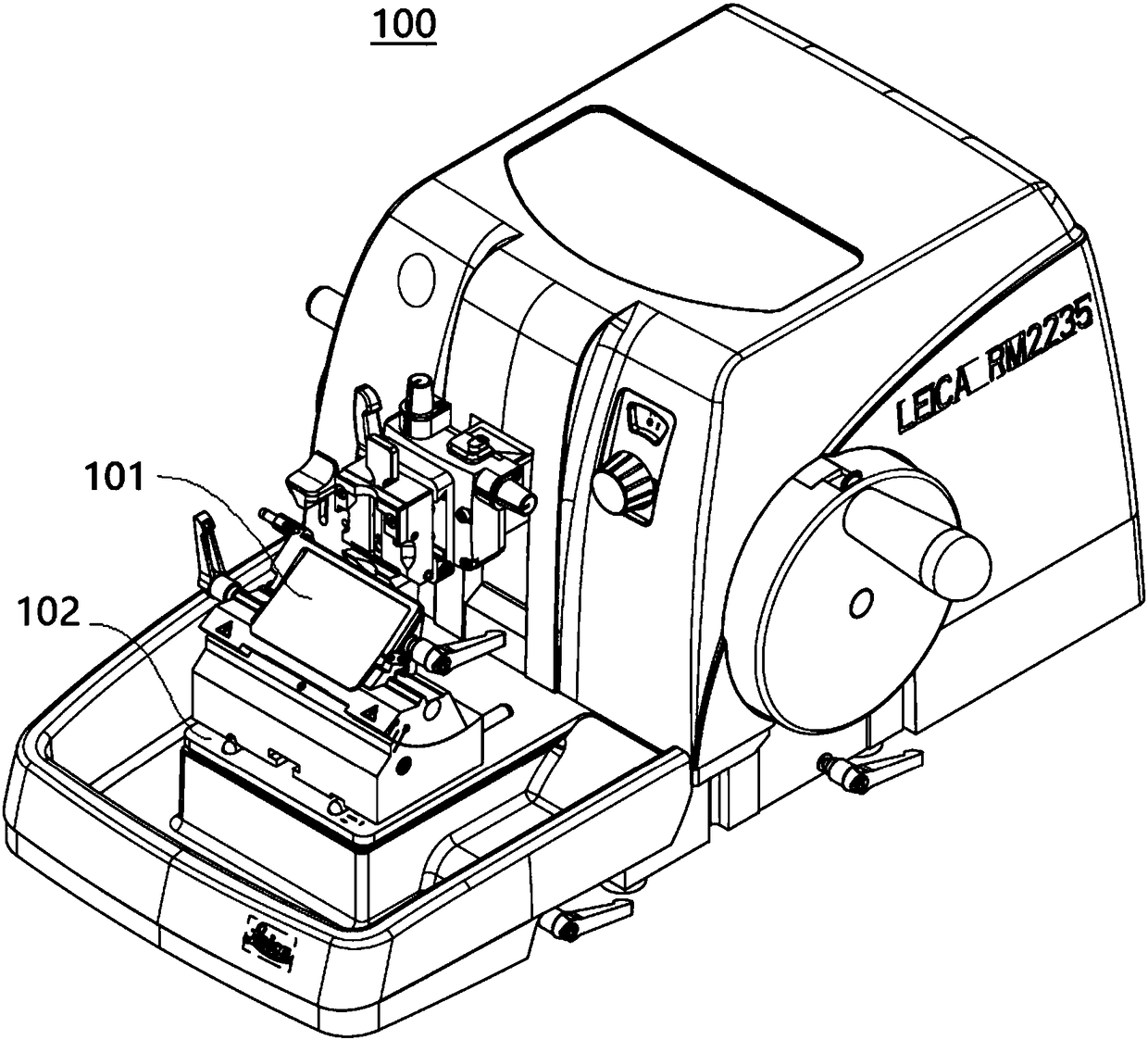
[0096] figure 1 A microtome 100 known in the prior art is shown. Such as figure 1 As shown, the microtome 100 includes a blade holder 101 and a mounting seat 102 . Wherein, the blade frame 101 is connected to the mounting base 102 .

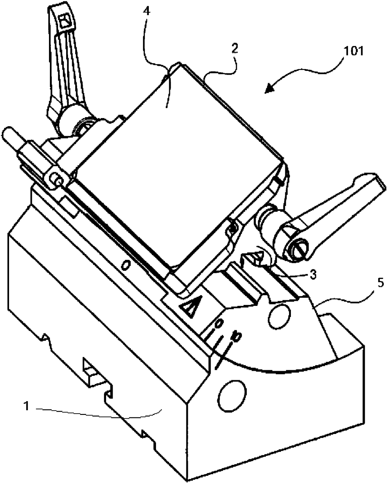
[0097] figure 2 show figure 1 The blade holder 101 of the microtome 100. Such as figure 2 As shown, the blade holder 101 includes a base 1 , a microtome blade 2 , a base 3 , a pressure plate 4 and a segmented curved member 5 . Wherein the base body 3 has an abutment surface, a pressure plate 4 is attached to the base body 3, the pressure plate 4 can be adjusted relative to the base body 3 to clamp the microtome blade 2 receive...


PUM


Abstract

The invention discloses a clamping device and a slicer with the same. The clamping device comprises a control part, a wedge part, a clamping part and a shell and is characterized in that the wedge part is provided with a first end, a second end and a first oblique surface between the first end and the second end, and the wedge part expands from the second end and the first end; the clamping part is provided with a second oblique surface, the first oblique surface and the second oblique surface are oppositely arranged, and the first oblique surface can move relative to the second oblique surface; the shell is provided with a first guide part, a second guide part and a cavity, the control part is mounted in the first guide part, the clamping part is mounted in the second guide part, and thewedge part is arranged in the cavity; by controlling the control part to move towards the wedge part, the control part contacts with the first end of the wedge part, pushes the wedge part to move andallows the first oblique surface of the wedge part to contact with the second oblique surface of the clamping part and move along the second oblique surface, and accordingly the pushing force, along afirst direction, of the control part is converted into clamping force, along a second direction, of the clamping part.

Description

technical field [0001] The present disclosure relates to the technical field of slicers, in particular, to a clamping device and a slicer with the clamping device. Background technique [0002] A microtome is used to cut thin slices from the sample. These sections are then placed on coverslips, processed appropriately, and then examined under a microscope. In slicer equipment, there are various clamping requirements, such as clamping blades and blade holders, etc. [0003] In U.S. Patent US 4690023, a clamping mechanism for a cutter of a slicer is described, which has a wedge-shaped jaw plate and an eccentric bolt, by properly rotating the eccentric bolt, the wedge-shaped jaw plate can be pressed against the blade, Or loosen the blade. When the user needs to clamp the object, the eccentric bolt is rotated; when the user loosens the object, the eccentric bolt is rotated in the opposite direction. In order to obtain a better clamping function, the user needs to provide a l...

Claims


Application Information

Patent Timeline
Patent Type & Authority Applications(China)
IPC IPC(8): G01N1/28G01N1/06
CPCG01N1/06G01N1/286G01N2001/2873G01N2001/065B25B5/02B25B5/06B25B5/166B26D7/2614G01N1/28
Inventor 范哲光郝相宇蒋小奇
Owner LEICA MICROSYST LTD SHANGHAI SHANGHAI
Why Eureka
Try Eureka