Control device for inner core tube of drain valve

A technology of control device and inner core tube, applied in valve device, valve operation/release device, valve details, etc., can solve problems such as button stroke error, error in rope production, and inability to achieve half-drain flushing.

Active Publication Date: 2016-03-02
LAB XIAMEN SANITARY FITTINGS
View PDF12 Cites 3 Cited by
  • Summary
  • Abstract
  • Description
  • Claims
  • Application Information

AI Technical Summary

Problems solved by technology

[0005] However, the defects of the prior art drain valves are: 1. When the control ends of the half-row buttons and the full-row buttons are set as pull cords, there are errors in the production of the stay cords, and at the same time, due to thermal expansion and contraction, the stay cords are driven inwardly. When the core tube is lifted, its stroke produces a large error, and the inner core tube cannot be lifted in place, so that the half row of stuck points of the inner core tube cannot be limited, and the half row of flushing cannot be realized; the control terminal setting of the half row of buttons and the full row of buttons When it is a button, due to the error in the production of the button, and the wear and tear caused by pressing at the same time, the stroke of the button will have a large error when driving the inner core tube to lift, and the inner core tube cannot be lifted in place, so that the half row of stuck points of the inner core tube cannot be restricted. position, unable to achieve half-row flushing

Method used


Image

  • Control device for inner core tube of drain valve
  • Control device for inner core tube of drain valve
  • Control device for inner core tube of drain valve

Examples


Embodiment Construction

[0039] The present invention will be described in detail below in conjunction with the accompanying drawings and specific embodiments.

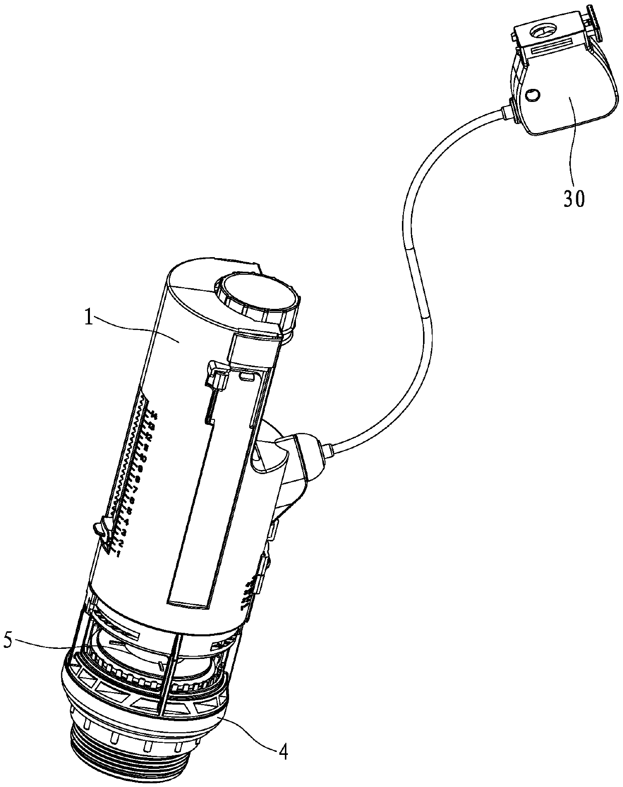
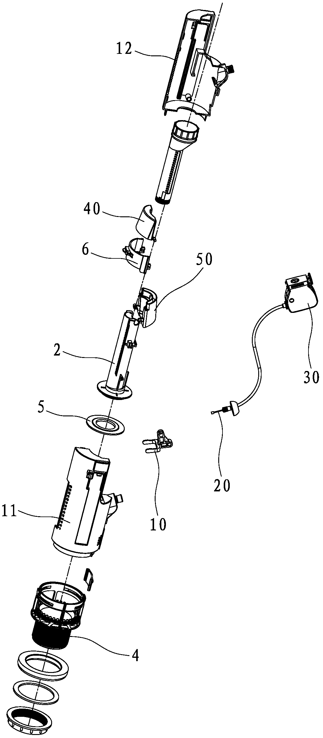
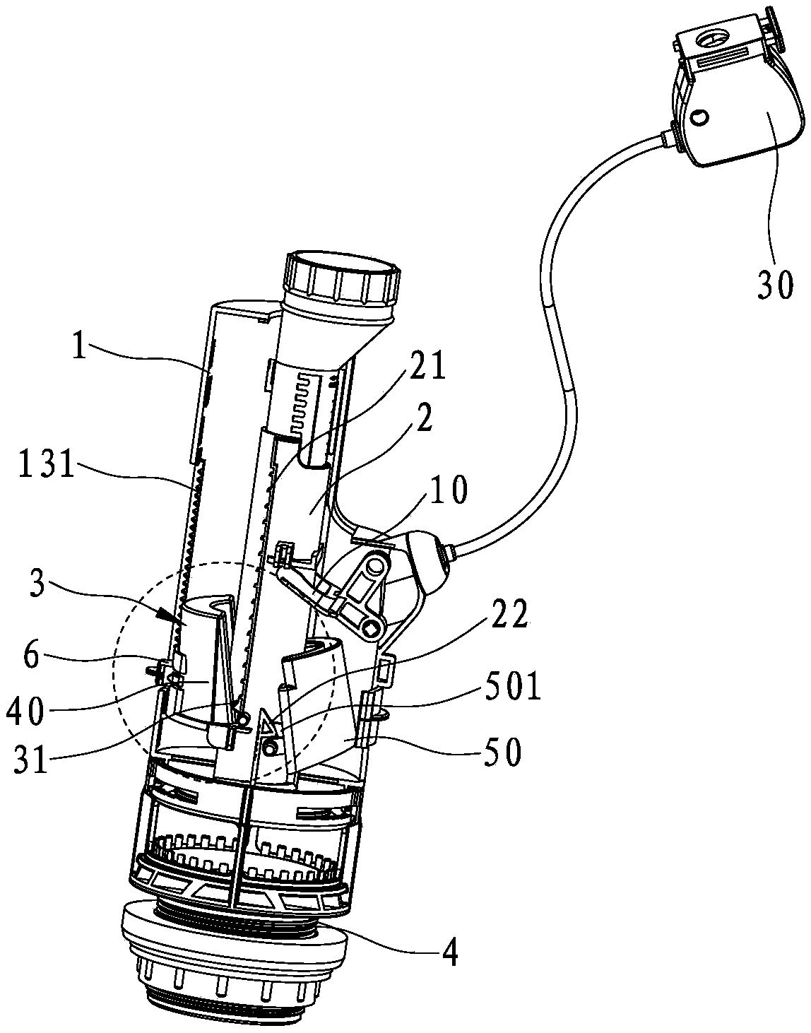
[0040] refer to Figure 1 to Figure 8a As shown, an inner core tube control device for a drain valve disclosed in the present invention includes a drain valve body 1 , an inner core tube 2 and a floating bucket 3 .

[0041] This embodiment takes the wire-controlled drain valve as an example. The wire-controlled mechanism drives the inner core tube to move. The wire-controlled mechanism usually includes a pull hook 10, a pull rope 20 and a wire control box assembly 30. The pull hook 10 is pivotally connected to the drain valve body 1. It is connected with the inner core tube 2, one end of the drawstring 20 is connected with the drag hook 10, and the other end of the drawstring 20 is connected with the wire control box assembly 30, and the half row of buttons and the full row of buttons (not shown in the figure) are installed on the wire contro...


PUM


Abstract

The invention discloses a control device for an inner core tube of a drain valve. The control device comprises a drain valve body, an inner core tube and a floating barrel; the inner core tube is mounted in the drain valve body, the inner core tube is driven to move in the drain valve body by half a row of buttons or a row of buttons, and the floating barrel is pivotally connected with a position inside the drain valve body and beside the inner core tube; a row of clamping points arranged at intervals are vertically arranged on the inner core tube, supporting points corresponding to the clamping points of the inner core tube are arranged on the floating barrel, the floating force stressed on the floating barrel is larger than the self gravity thereof, the floating barrel swings towards the inner core tube, the supporting points of the floating barrel are limited on the clamping points of the inner core tube, and when the floating force stressed on the floating barrel is smaller than the self gravity thereof, the floating barrel swings towards the drain valve body, and the supporting points of the floating barrel are independent of the clamping points of the inner core tube.

Description

technical field [0001] The invention relates to the technical field of drain valves, in particular to an inner core tube control device for drain valves. Background technique [0002] In the prior art, the drain valve is generally composed of a body, a half row of buttons, a full row of buttons, an inner core pipe, a half row of floating buckets, a full row of floating buckets and a water sealing member. The control end of the half-row button and the full-row button is connected to the inner core tube, the control end is a button or a pull cord, the inner core tube is installed in the body, and the control end of the half-row button or the full row button drives the inner core tube in the body The lifting of different strokes up and down, the half row of floating buckets and the full row of floating buckets are installed in the body next to the inner core tube, and the water sealing parts are installed at the lower end of the inner core tube. [0003] When the half-row is f...

Claims


Application Information

Patent Timeline
Patent Type & Authority Applications(China)
IPC IPC(8): F16K31/18
CPCF16K31/18
Inventor 刘永茂张子鹏
Owner LAB XIAMEN SANITARY FITTINGS
Why Eureka
Try Eureka