

Automatic Steel Loading Control Method for Regenerative Walking Heating Furnace
A control method and heating furnace technology, applied in the direction of electrical program control, sequence/logic controller program control, etc., can solve the problems of large vibration, inaccurate positioning, high replacement rate, etc., and achieve error reduction, accurate positioning, and positioning short time effect
- Summary
- Abstract
- Description
- Claims
- Application Information
AI Technical Summary
Problems solved by technology
Method used
Image

Examples
Embodiment Construction
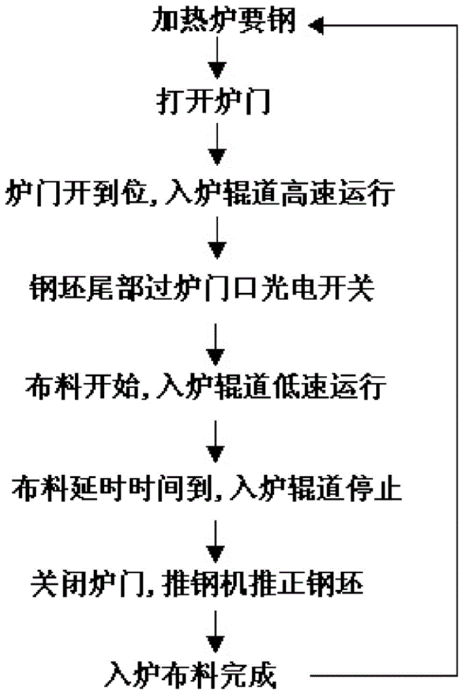
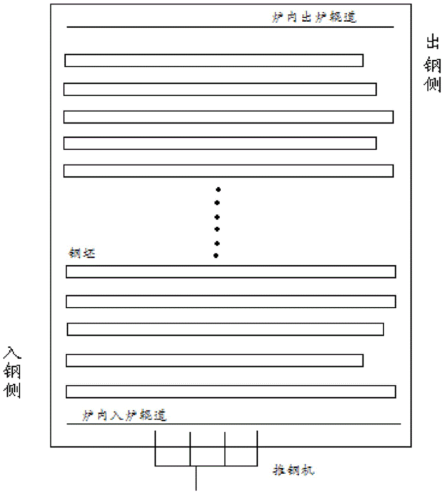
[0021] see Figure 1 to Figure 4 , an automatic steel loading control method for a regenerative walking heating furnace, comprising the following steps:
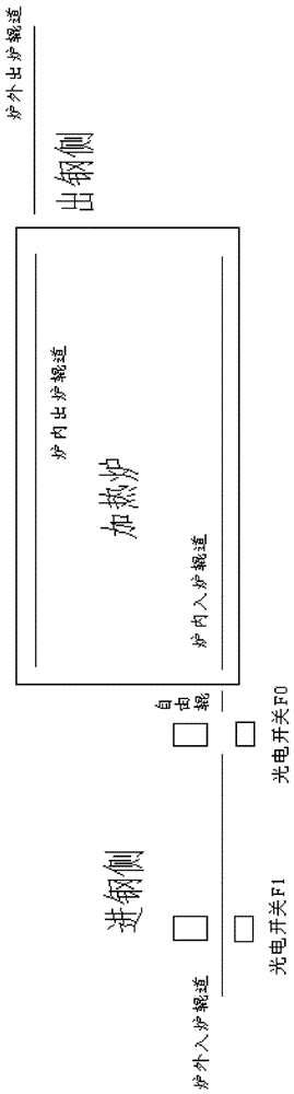
[0022] 1) Set the first photoelectric switch F1 next to the roller table outside the furnace, set the second photoelectric switch F0 between the roller table outside the furnace and the free roller in front of the furnace, and set the time in the control system of the roller table in the heating furnace interval T1 and time interval T2;
[0023] 2) Start the roller table outside the furnace at high speed to transport the billet to the heating furnace. When the head of the billet reaches the position of the first photoelectric switch F1, if the heating furnace sends a signal allowing steel loading and the furnace door is opened in place, the rollers entering the furnace outside the furnace The furnace continues to run at high speed, and the roller table in the furnace runs at high speed, go to step 4); if the heating furnace...
PUM
 Abstract
Description
Claims
Application Information