
Annular LED illumination device capable of adjusting light-emitting direction

A lighting device and light-emitting direction technology, applied in the field of lighting, can solve problems such as damage to LED lamps and high requirements for driving components

Inactive Publication Date: 2016-03-02
JIANGSU MODERN LIGHTING GRP CO LTD
View PDF0 Cites 0 Cited by
  • Summary
  • Abstract
  • Description
  • Claims
  • Application Information

AI Technical Summary

Problems solved by technology

[0003] In the traditional lighting scheme, it is affected by factors such as the shape of the light source, the installation size, and the power level. Generally, the adjustment of LED light emission in the prior art generally uses the control method of the driving current to adjust the light emission brightness. The adjustment method often has high requirements on the driving components, and the LED lamp may be damaged when the brightness is adjusted many times

Method used


Image

  • Annular LED illumination device capable of adjusting light-emitting direction
  • Annular LED illumination device capable of adjusting light-emitting direction

Examples


Embodiment Construction

[0011] In order to make the object, technical solution and advantages of the present invention clearer, the present invention will be further described in detail below in conjunction with the accompanying drawings and embodiments. It should be understood that the specific embodiments described here are only used to explain the present invention, not to limit the present invention. In addition, the technical features involved in the various embodiments of the present invention described below can be combined with each other as long as they do not constitute a conflict with each other.

[0012] For reasons of convenience only, in the following description, specific directional terms, such as "up", "down", "left", "right", etc., are used with reference to the corresponding drawings and It should not be regarded as a limitation on the present invention, and when the defined direction of the drawings changes, the directions indicated by these words should be interpreted as correspo...


PUM


Abstract

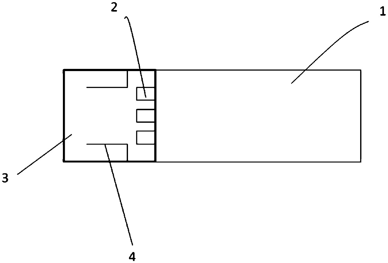
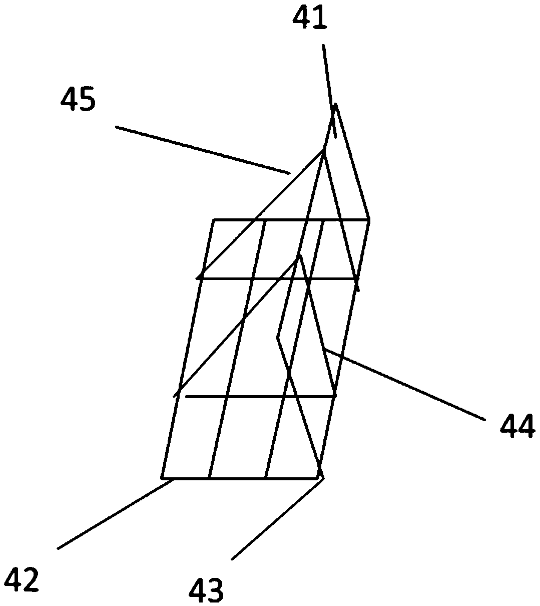
The invention discloses an annular LED illumination device capable of adjusting the light-emitting direction. The annular LED illumination device capable of adjusting the light-emitting direction is characterized in that the illumination device comprises an annular lamp structure body and an annular lamp housing; LED light sources are installed on the outer side of the annular lamp structure body and arranged at equal intervals in the circumferential direction; the illumination device further comprises a fixing assembly; the illumination device is fixed to a ceiling through the fixing assembly; the annular lamp housing is a transparent or semi-transparent lamp housing which is made of acrylic materials or polycarbonate materials; controllable and adjustable fan blades which can be adjusted up and down in the axial direction are fixedly installed on the upper surface and the lower surface, in the axial direction, of the illumination device, so that the light-emitting direction of the LED light sources is adjusted. According to the annular LED illumination device capable of adjusting the light-emitting direction, the illumination brightness and the illumination direction can be adjusted in a user-friendly mode.

Description

technical field [0001] The invention belongs to the field of lighting, and more particularly relates to a ring-shaped LED lighting device capable of adjusting the direction of light emission. Background technique [0002] In the field of indoor lighting technology, it has always been the direction for engineers to improve and develop to achieve effective control of lamps and meet the needs of the human eye for light in various situations. [0003] In the traditional lighting scheme, it is affected by factors such as the shape of the light source, the installation size, and the power level. Generally, the adjustment of LED light emission in the prior art generally uses the control method of the driving current to adjust the light emission brightness. The adjustment method often has high requirements on the driving components, and the LED lamp may be damaged when the brightness is adjusted many times. Contents of the invention [0004] In view of the above defects or improv...

Claims


Application Information

Patent Timeline
IPC IPC(8): F21K9/20F21V3/04F21V23/00F21V14/08F21Y115/10
CPCF21V3/06F21V14/08F21V23/003
Inventor 朱文明
Owner JIANGSU MODERN LIGHTING GRP CO LTD
Learn More