
Holographic projection display cabinet

A holographic projection and display cabinet technology, applied in the field of holographic projection, can solve problems such as blind spots and inconvenient viewing for audiences, and achieve the effects of low energy consumption, small size and high brightness

Inactive Publication Date: 2016-03-02
重庆触视科技有限公司
View PDF7 Cites 10 Cited by
  • Summary
  • Abstract
  • Description
  • Claims
  • Application Information

AI Technical Summary

Problems solved by technology

[0004] However, the formation of dynamic images in the projection system requires the use of projectors or electronic display screens, and for the display of products and cultural relics, it is only necessary to form static three-dimensional projections of products and cultural relics, and then rotate the static three-dimensional projections to form static images. Three-dimensional projection can be completed only by using slides and lighting sources. Compared with projectors or electronic display screens used to form dynamic three-dimensional projections, the structure is simpler and the cost is lower; However, the holographic projection is only rotated along one axis. Since the two ends of the holographic projection rotation axis cannot face the audience, it will form a dead angle for viewing, which is not convenient for the audience to watch.

Method used


Image

  • Holographic projection display cabinet

Examples


Embodiment

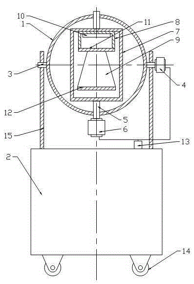
[0018] Embodiment A holographic projection display cabinet is basically as attached figure 1 Shown: including display stand and cabinet body 2, the height of cabinet body 2 is 1.3m, rollers 14 are installed at the bottom of cabinet body 2, the display stand is ring 1, and two first Rotating shafts 3, two first rotating shafts 3 are on the same diameter line of the ring 1, one of the first rotating shafts 3 is connected with a first motor 4, each rotating shaft is hinged with a support rod 15, and the support rod 15 is vertically fixed On the cabinet body 2, two second rotating shafts 5 perpendicular to the first rotating shaft 3 are hinged on the ring 1, and one of the second rotating shafts 5 is connected with a second motor 6, a first motor 4 and a second motor 6 Both are connected to the switch 13, the switch 13 is fixed on the cabinet body 2, the two second rotating shafts 5 are on the same diameter line of the ring 1, and a rotating frame 7 is fixed on the end surface of ...


PUM

PropertyMeasurementUnit
Heightaaaaaaaaaa

Abstract

The invention discloses a holographic projection display cabinet, comprising a display stand and a cabinet body; the display stand is a circular ring; two first rotation shafts are fixed on the side of the outer circle of the circular ring; the two first rotation shafts are arranged on the diameter line of the circular ring, wherein the first rotation shaft is connected to a first motor; each rotation shaft is hinged with a support rod which is vertically fixed on the cabinet body; the circular ring is hinged with two second rotation shafts which are perpendicular to the first rotation shaft, wherein one of the second rotation shaft is connected to a second motor; two second rotation shafts are positioned on the diameter of the circular ring; the two second rotation shafts are positioned on the end surface inside the circular ring and commonly fix a rotation frame; a projection box is fixed on the inner side of the rotation frame; the projection box is internally provided with a projection light source; the bottom of the projection box is a transparent glass plate; the bottom of the transparent glass plate is fixedly provided with a four-side cone body consisting of four trapezoid glass pieces which are plated with holographic films The invention provides a rotatable and no-watching dead angle holographic projection display cabinet which displays the static holographic projection.

Description

technical field [0001] The invention relates to the field of holographic projection, in particular to a holographic projection display cabinet. Background technique [0002] Holographic projection is a method of recording and reproducing real three-dimensional images of objects by using the principles of interference and diffraction. For holographic projection, it is often necessary to use a holographic projection display cabinet. Holographic projection technology is suitable for product exhibitions, car clothing conferences, stage shows, interactions, bar entertainment, and venue interactive projections. [0003] The holographic projection display cabinet includes a display stand and a cabinet. The display stand is a four-sided cone composed of four trapezoidal glass coated with a holographic film. Below the display stand is a cabinet installed with a projection system. In order to display the three-dimensional projection to the audience in an all-round and dynamic way, a...

Claims


Application Information

Patent Timeline
IPC IPC(8): G03B35/18G09F19/18
CPCG03B35/18G09F19/18
Inventor 任博
Owner 重庆触视科技有限公司
Learn More