Fixed seat of box-type transformer

A box-type transformer and fixing seat technology, applied in the direction of transformer/reactor installation/support/suspension, etc., can solve the problems of affecting the safety of dry-type transformers, unreasonable base structure, inconvenient coil positioning, etc., and achieve high reliability. , The effect of improving sliding efficiency and easy operation

Inactive Publication Date: 2016-03-02
重庆吉能变压器有限公司
View PDF0 Cites 2 Cited by
  • Summary
  • Abstract
  • Description
  • Claims
  • Application Information

AI Technical Summary

Problems solved by technology

[0002] In the existing technology, the base structure of the traditional dry-type transformer is not reasonable enough, the positioning is inconvenient when installing the coil, and the shock absorption performance is not good. The coil of the dry-type transformer is easily affected by vibration and loosens, which in turn affects the use of the dry-type transformer Safety
At present, the transformer base of most manufacturers adopts channel steel structure. The lower plane of the base is in contact with the ground, and the upper end faces of the two sides are in contact with the transformer core, which is prone to generate large noise during operation. In addition, the traditional transformer fixing seat It is built with sealed plates, and the general plate structure has poor heat dissipation due to the sealed structure, so a base is needed to meet the dual requirements of high heat dissipation efficiency and convenient installation, so a box is needed Type transformer mount to meet this requirement

Method used


Image

  • Fixed seat of box-type transformer
  • Fixed seat of box-type transformer
  • Fixed seat of box-type transformer

Examples


Embodiment Construction

[0014] In order to make the technical means, creative features, goals and effects achieved by the present invention easy to understand, the present invention will be further described below in conjunction with specific embodiments.

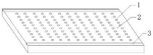
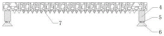
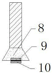
[0015] see figure 1 , figure 2 and image 3 , the present invention provides a technical solution: a box-type transformer fixing seat, including a main part and an adjusting part, the main part is composed of a cooling hole 1, a base 2, a chute 3 and a reinforcing rib 7, and the base 2 is a cubic plate structure, the base 2 is arranged parallel to the horizontal plane, the base 2 is distributed with cooling holes 1, the cooling holes 1 run through the upper end surface and the lower end surface of the base 2, the lower end surface of the base 2 is fixed with reinforcing ribs 7, and the reinforcing ribs 7 are parallel to each other Arrangement, the reinforcement of the base 2 is achieved by adding reinforcing ribs 7, thereby preventing the inwar...


PUM


Abstract

The invention provides a fixed seat of a box-type transformer. A base is of a cubic plate-shaped structure and is arranged in parallel to a horizontal plane, cooling holes are distributed on the base and pass through the upper end surface and the lower end surface of the base, reinforcement ribs are fixedly arranged on the lower end surface of the base and arranged in parallel to one another, two sliding grooves are formed on the upper end surface of the base, a roller is arranged at the lower end of a clamping block, the clamping block and the roller are connected via a rolling shaft, and four fixed legs are arranged at four corners of the lower end of the base. With the additional arrangement of the reinforcement ribs, the base is reinforced, and the situation that the base is inwards sunken due to stress concentration is further prevented; with the design of the sliding grooves and the clamping blocks, the installation efficiency is improved, and the installation process is not limited to the positions of screw holes; and with the design of the rollers, the sliding efficiency of the clamping blocks is effectively improved, and the sliding grooves are further prevented from being damaged caused by overhigh friction force.

Description

technical field [0001] The invention relates to a box-type transformer fixing seat, which belongs to the field of transformer accessories. Background technique [0002] In the existing technology, the base structure of the traditional dry-type transformer is not reasonable enough, the positioning is inconvenient when installing the coil, and the shock absorption performance is not good. The coil of the dry-type transformer is easily affected by vibration and loosens, which in turn affects the use of the dry-type transformer Safety. At present, the transformer base of most manufacturers adopts channel steel structure. The lower plane of the base is in contact with the ground, and the upper end faces of the two sides are in contact with the transformer core, which is prone to generate large noise during operation. In addition, the traditional transformer fixing seat It is built with sealed plates, and the general plate structure has poor heat dissipation due to the sealed str...

Claims


Application Information

Patent Timeline
Patent Type & Authority Applications(China)
IPC IPC(8): H01F27/06
Inventor 张勇周安根
Owner 重庆吉能变压器有限公司
Why Eureka
Try Eureka