
Control plane body milling tool
A milling and tooling technology, applied in the field of machining, can solve the problems of difficult to guarantee the machining accuracy of parts, difficult clamping of the middle groove and left bevel, and low efficiency, so as to broaden the processing limitations, easily adapt to production and processing, cost reduction effect
Patent Information
- Authority / Receiving Office
- CN · China
- Patent Type
- Applications(China)
- Current Assignee / Owner
- Publication Date
- 2016-03-09
- Estimated Expiration
- Not applicable · inactive patent
Smart Images
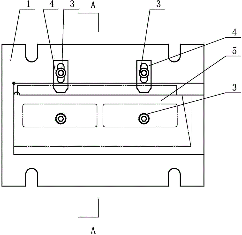
Figure 1 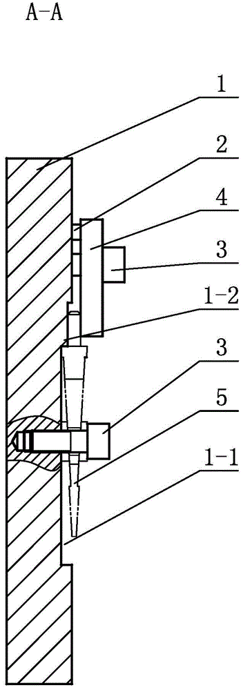
Figure 2 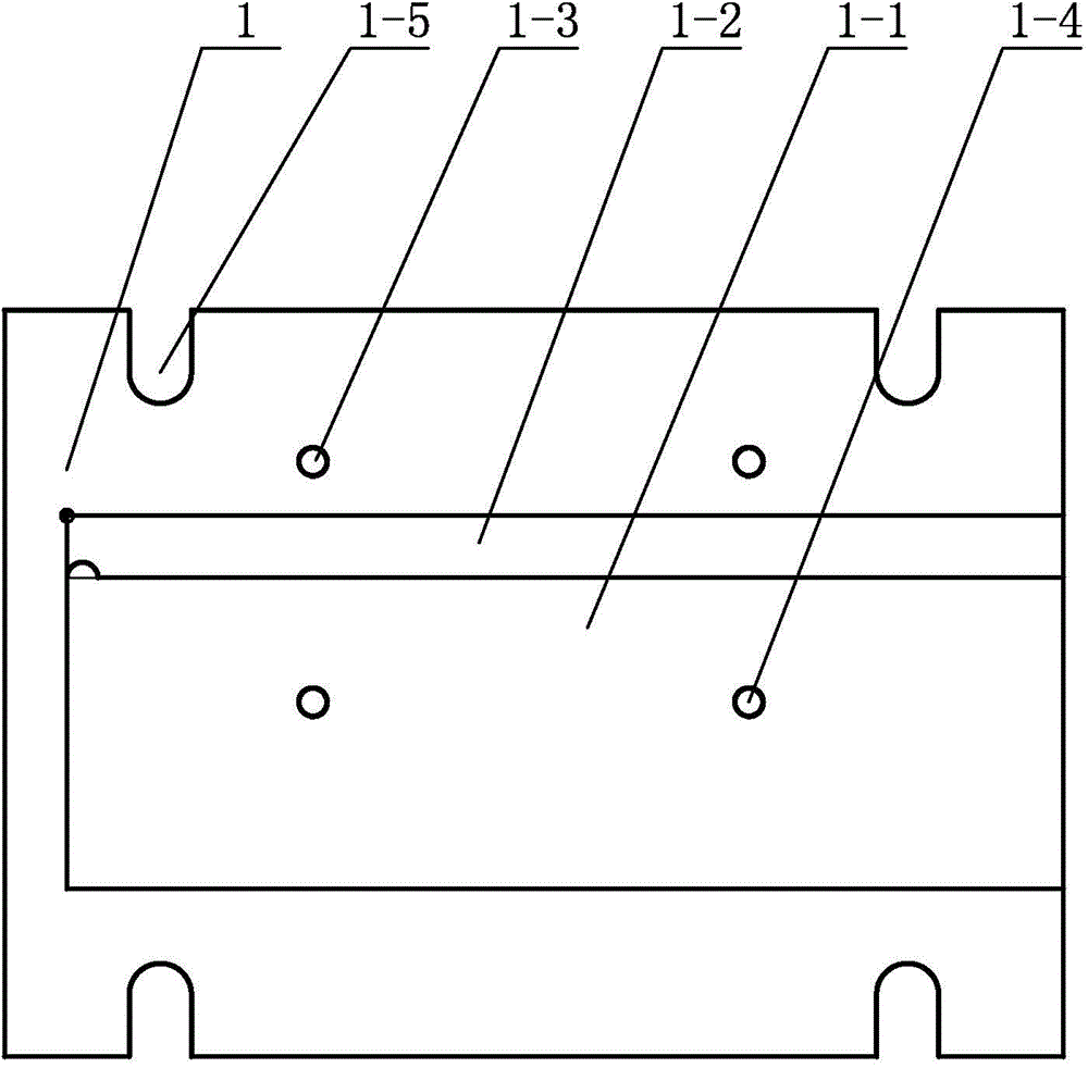
Figure 3
Abstract
Description
technical field
[0001] The invention relates to a milling tool, in particular to a rudder surface milling tool, which belongs to the field of mechanical processing. Background technique
[0002] In the processing of the existing rudder surface parts, the middle groove and the left hypotenuse are processed by slow wire cutting, which takes a long time and high processing cost; in order to reduce the cost, the milling method is used to process the two parts, but Clamping is difficult, efficiency is low, and the machining accuracy of parts is difficult to guarantee. Contents of the invention
[0003] The invention aims to solve the problems of difficult clamping of the middle groove and the left hypotenuse of the milling process of the rudder surface body parts, low efficiency, and difficulty in ensuring the machining accuracy of the parts, and further designs the rudder surface body milling tooling.
[0004] The technical scheme adopted by the present invention to solve the...
Examples
specific Embodiment approach 1
[0007] Specific implementation mode one: combine Figure 1 to Figure 3 Describe this embodiment, a kind of rudder surface body milling tooling described in this embodiment includes a base plate 1, two pressure plates 4 and four M10 socket head bolts 3, the base plate 1 is a rectangular plate body, the base plate 1 is horizontally arranged, and the upper surface of the base plate 1 There is a rectangular groove 1-1 in the middle of the rectangular groove 1-1, a shoulder 1-2 is provided on one side of the rectangular groove 1-1, and two first screw holes 1-3 are provided on one side of the upper surface of the bottom plate 1 along the length direction. , the rectangular groove 1-1 is provided with two second screw holes 1-4 along the length direction, two mounting gaps 1-5 are opened on each side edge of the bottom plate 1, and the two pressure plates 4 pass through two M10 inner hexagon bolts 3 is installed in the two first screw holes 1-3, and the workpiece 5 is installed in t...
specific Embodiment approach 2
[0008] Specific implementation mode two: combination Figure 1 to Figure 3 To illustrate this embodiment, the rudder surface body milling tool described in this embodiment further includes two pads 2 , and one pad 2 is provided between the lower surface of each pressing plate 4 and the upper surface of the base 1 .
[0009] The technical effect of this embodiment is: with such arrangement, other components and connections are the same as those in the first embodiment.
specific Embodiment approach 3
[0010] Specific implementation mode three: combination Figure 1 to Figure 3 Describe this embodiment, the length of the bottom plate 1 of the steering surface body milling tool described in this embodiment is 340mm, the width of the bottom plate 1 is 240mm, and the thickness of the bottom plate 1 is 30mm. Other compositions and connections are the same as those in Embodiment 1 or 2.