Automatic locking device for tank cover of pressure tank

An automatic locking and pressure tank technology, applied in the field of pressure tanks, can solve the time-consuming and labor-intensive problems of opening and closing tank lids, and achieve the effects of reducing friction, locking fastness and stability, and good stability

Active Publication Date: 2016-03-09
新界泵业(浙江)有限公司
View PDF6 Cites 0 Cited by
  • Summary
  • Abstract
  • Description
  • Claims
  • Application Information

AI Technical Summary

Problems solved by technology

[0002] At present, the general way of connecting the pressure tank and the tank cover is to use flanges and bolts. The disadvantage is that it takes time and effort to open and close the tank cover. The difference is that it takes time and effort to open and close the tank cover; the second is to use the hinged screw on the pressure tank, and the screw is rotated to the opening groove of the tank cover to tighten it with a nut; the third is to use the rotating tank cover to make the pressure tank mouth and the tank cover circumferentially The arc-shaped teeth interlock and lock the tank cover. The disadvantage is that it takes time and effort to open and close the tank cover. It is suitable for pressure tanks with relatively high pressure.

Method used


Image

  • Automatic locking device for tank cover of pressure tank
  • Automatic locking device for tank cover of pressure tank

Examples


Embodiment Construction

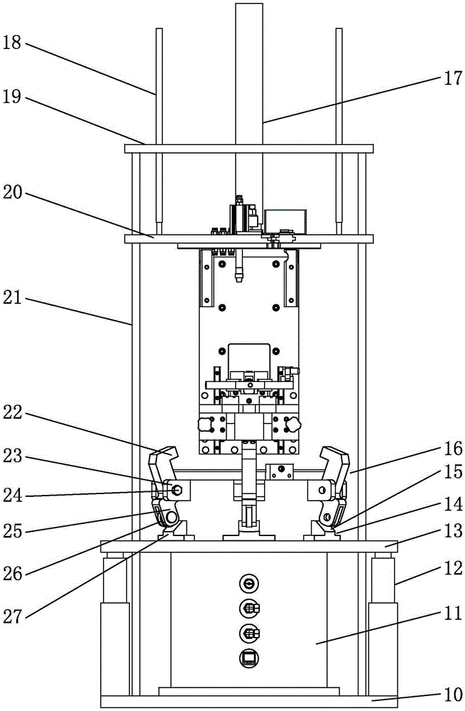
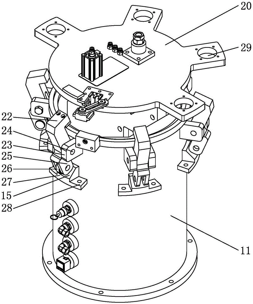
[0022] Below in conjunction with accompanying drawing, the present invention will be further described with specific embodiment, see figure 1 — figure 2 :

[0023] The tank cover automatic locking device of the pressure tank includes the tank body 11 of the pressure tank and the tank cover 20 covering the opening of the tank body 11. The outer wall of the tank body 11 opening is provided with more than three fixing seats at intervals in the circumferential direction. 23, the hinge part of the middle part of the lock block 16 is hinged on the fixed seat 23 through the hinge shaft 24, the upper side of the lock block 16 has a lock hook 22, and the lower side has a drive arm 25, and the lock hook 22 of the lock block 16 is connected to the drive arm 25 and The hinge part in the middle is an integral structure, and the lower side of the driving arm 25 is provided with a driving ring 13 driven by a power device to move up and down and sleeved on the outer wall of the tank body 11...


PUM


Abstract

The invention belongs to the technical field of pressure tanks, and relates to an automatic locking device for a tank cover of a pressure tank. The pressure tank comprises a pressure tank body and the tank cover covering an opening of the tank body. Three or more fixing seats are arranged on the outer wall of the opening of the tank body at intervals in the circumferential direction. A hinging portion in the middle of each locking block is hinged to the corresponding fixing seat through a hinging shaft, a locking hook is arranged on the upper side of each locking block, and a driving arm is arranged on the lower side of each locking block. A driving ring is arranged on the lower sides of the driving arms, driven by a power device to move up and down and mounted on the outer wall of the pressure tank in a sleeving mode. The driving ring is provided with wedge blocks driving the driving arms to rotate around the hinging shafts. After the tank cover covers the opening of the tank body and the power device drives the driving ring and the wedge blocks to move upwards, the wedge blocks drive the driving arms to rotate so as to enable the locking hooks of the locking blocks to clamp the upper surface of the tank cover, and automatic locking of the tank body and the tank cover is achieved. The automatic locking device has the advantages that the tank body and the tank cover are automatically locked, locking stability is good, friction force is small, and the automatic locking device is suitable for automatic locking between the tank body and the tank cover of a small pressure container.

Description

technical field [0001] The invention belongs to the technical field of pressure tanks, in particular to an automatic locking device for a tank cover of a pressure tank. Background technique [0002] At present, the general way of connecting the pressure tank and the tank cover is to use flanges and bolts. The disadvantage is that it takes time and effort to open and close the tank cover. The difference is that it takes time and effort to open and close the tank cover; the second is to use the hinged screw on the pressure tank, and the screw is rotated to the opening groove of the tank cover to tighten it with a nut; the third is to use the rotating tank cover to make the pressure tank mouth and the tank cover circumferentially The arc-shaped teeth of the arc-shaped teeth engage with each other to lock the tank cover. The disadvantage is that it takes time and effort to open and close the tank cover, and it is suitable for pressure tanks with relatively high pressure. Conte...

Claims


Application Information

Patent Timeline
Patent Type & Authority Applications(China)
IPC IPC(8): F16J13/02
CPCF16J13/02
Inventor 毛益波潘巍巍
Owner 新界泵业(浙江)有限公司
Why Eureka
Try Eureka