
Structure and injection mold with functions of ejection and core pulling

An injection mold and ejection technology, which is applied in the field of structure and injection mold, can solve problems such as difficulty in guaranteeing the quality of ejection

Active Publication Date: 2017-12-12
SHENZHEN SKYWORTH PRECISION TECH
View PDF4 Cites 2 Cited by
  • Summary
  • Abstract
  • Description
  • Claims
  • Application Information

AI Technical Summary

Problems solved by technology

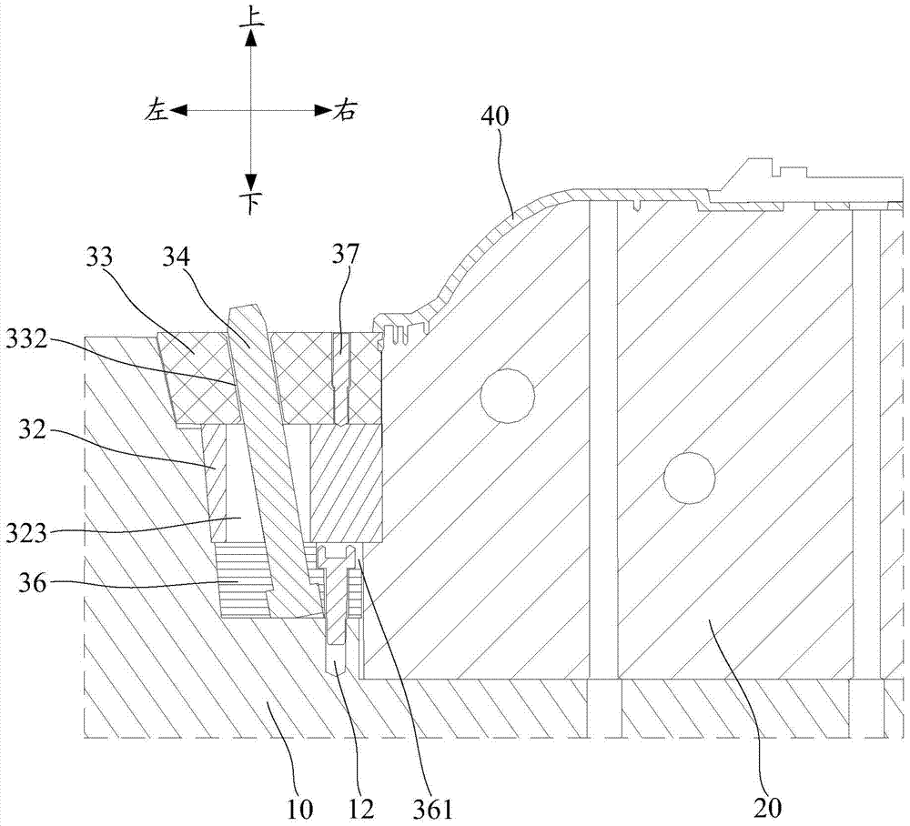
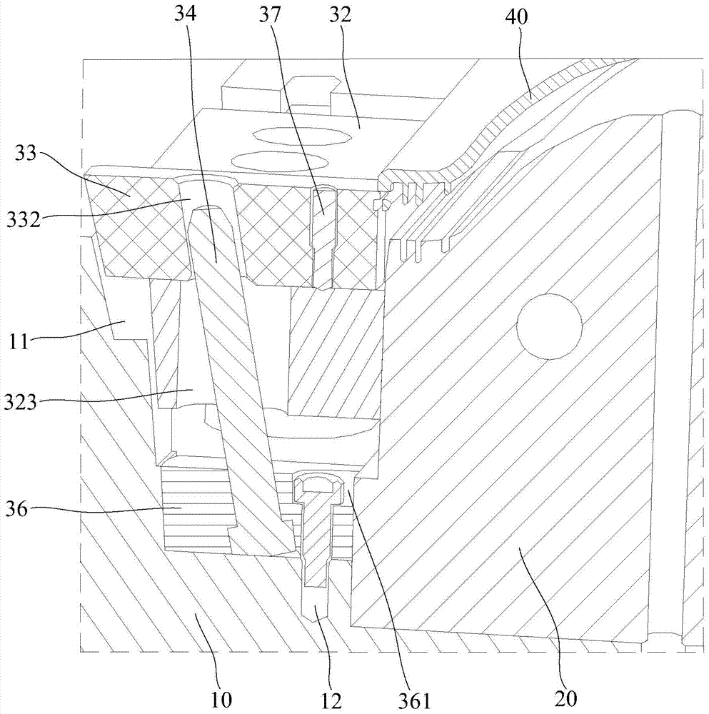
However, in the design of traditional injection molds, once the slider structure is set to realize the buckle core pulling on the side of the injection molded product, it will not be possible to set push blocks or push squares on the edge of the injection molded product. In this way, the ejection quality of this type of injection molded product hard to guarantee

Method used


Image

  • Structure and injection mold with functions of ejection and core pulling
  • Structure and injection mold with functions of ejection and core pulling
  • Structure and injection mold with functions of ejection and core pulling

Examples


Embodiment Construction

[0030] The following will clearly and completely describe the technical solutions in the embodiments of the present invention with reference to the accompanying drawings in the embodiments of the present invention. Obviously, the described embodiments are only part of the embodiments of the present invention, not all of them. Based on the embodiments of the present invention, all other embodiments obtained by persons of ordinary skill in the art without creative efforts fall within the protection scope of the present invention.

[0031] It should be noted that all directional indications (such as up, down, left, right, inside, outside...) in the embodiments of the present invention are only used to explain the relationship between the components in a certain posture (as shown in the accompanying drawings). Relative positional relationship, movement conditions, etc., if the specific posture changes, the directional indication will also change accordingly.

[0032] In addition, ...


PUM


Abstract

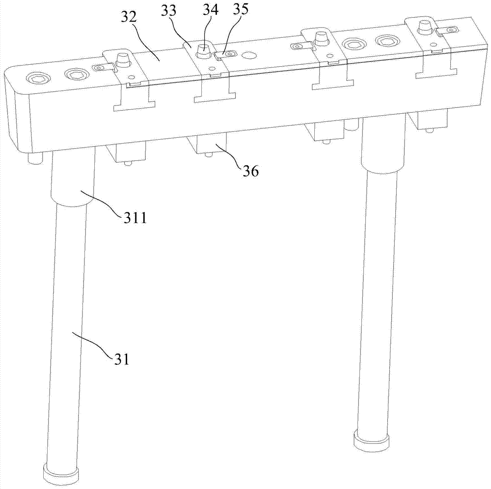
The invention discloses a structure with ejection and core-pulling functions and an injection mold. The structure with the ejection and core-pulling functions comprises push rods, a push block, sliding blocks and inclined guide pillars, and the push rods penetrate through a lower mold plate of the injection mold and are connected with the push block. The push block is used for pushing and ejecting out an injection product, sliding grooves penetrating through the inner side and the outer side of the push block are concavely formed in the upper end face of the push block, and avoiding holes penetrating through the bottoms of the sliding grooves are formed; the sliding blocks are accommodated in the sliding grooves in a matched mode and can slide outwards along the sliding grooves; each sliding block is provided with a core pulling hole which obliquely extends outwards from the lower end face of the sliding block to the upper end face of the sliding block from bottom to top; the lower ends of the inclined guide pillars are fixed to the lower mold plate, and the upper ends of the inclined guide pillars penetrate through the corresponding avoiding holes and then penetrate into the core pulling holes in a matched mode; the extending direction of the inclined guide pillars is consistent with the extending direction of the core pulling holes. By means of the technical scheme, while the push block is used for ejecting out the injection product, core pulling of buckling positions of the side faces of the injection product through the sliding blocks is achieved.

Description

technical field [0001] The invention relates to the technical field of injection molds, in particular to a structure and an injection mold with functions of ejection and core pulling. Background technique [0002] In the design of traditional injection molds, for large-scale cap-shaped products, when designing the ejection structure, the lower template usually sets push blocks or push squares corresponding to the edges of the injection molded products, so as to ensure that there are enough force-bearing surfaces when the injection molded products are ejected. In this way, the phenomenon of ejection deformation or bursting of the product can be avoided. As the assembly type of injection molding products changes, buckles are often provided on the side of the edge of the injection molding product in order to reduce the assembly gap, simplify the assembly process, and improve assembly efficiency; this type of injection molding product needs to be provided with a slider structure...

Claims


Application Information

Patent Timeline
Patent Type & Authority Patents(China)
IPC IPC(8): B29C45/33B29C45/40
CPCB29C45/33B29C45/332B29C45/4005B29C2045/338
Inventor 袁建忠张松平蔚建
Owner SHENZHEN SKYWORTH PRECISION TECH
Learn More