Stamping die with material ejection function

A technology for stamping dies and functions, applied in the field of stamping dies with the function of ejecting materials, to achieve the effects of improving stamping and discharging speed, reasonable design, and simple structure

Inactive Publication Date: 2017-06-23
SUZHOU HUICHENG PRECISION MOLD
View PDF7 Cites 2 Cited by
  • Summary
  • Abstract
  • Description
  • Claims
  • Application Information

AI Technical Summary

Problems solved by technology

[0003] The main technical problem to be solved by the present invention is to provide a stamping die with the function of ejecting materials, which can solve the above-mentioned shortcomings existing in the existing stamping dies

Method used


Image

  • Stamping die with material ejection function

Examples


Embodiment 1

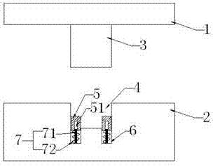
[0017] A stamping die with the function of ejecting materials, comprising an upper die 1 and a lower die 2, the lower surface of the upper die 1 has a punch 3, and the upper surface of the lower die 2 has a punch that matches the size of the punch 3 The stamping groove 4.

[0018] A jacking block 5 is also installed in the punching groove 4, and the two symmetrical side walls at the bottom of the punching groove 4 are chiseled with a cavity 6 that communicates with the bottom surface of the punching groove and matches the width of the jacking block 5, An elastic support mechanism 7 is also fixed in the cavity 6, and the lower end surface of the ejector block 5 is installed in the cavity 6 through the elastic support mechanism 7, and when the elastic support mechanism is in a free-to-expand state, the upper end surface of the ejector block is positioned at the punching position. in slot 4. The size relationship between the jacking block, the cavity and the stamping groove is: ...

Embodiment 2

[0022] The difference from Embodiment 1 is that the cavity 6 is located in the middle of the stamped groove 4 .

[0023] The working principle of the stamping die of the present invention is: in the process of stamping the stamping die, the ejector block is compressed by the punch until it is completely retracted into the cavity, and at this time the support spring in the spring telescopic mechanism is compressed to support The rod also goes deep into the hole groove of the ejector block; when the punch is punched, the punch is driven by the upper die to move upwards and leave the punching groove. During this process, the pressure from the punch on the ejector block disappears, supporting The spring rebound drives the ejector block to move upwards. On the one hand, the material belt is ejected out of the stamping groove, and on the other hand, the stamped product is jacked up, which is convenient for the manipulator to take out the material.


PUM


Abstract

The invention discloses a stamping die with a material ejection function. The stamping die comprises an upper die body and a lower die body. A punch is arranged on the lower surface of the upper die body. Stamping grooves matched with the punch in size are formed in the upper surface of the lower die body. Material ejection blocks are mounted in the stamping grooves. Cavities which are matched with the material ejection blocks in size and communicate with the bottom faces of the stamping grooves are dug in the bottoms of the stamping grooves. The lower end faces of the material ejection blocks are mounted in the cavities through elastic support mechanisms. The upper end faces of the material ejection blocks are located in the stamping grooves. The stamping die with the material ejection function is simple in structure and reasonable in design; and the material ejection blocks and the elastic support mechanisms are arranged in the stamping grooves, a material ejection system is formed and accordingly used for ejecting material strips and stamping pieces out after stamping is completed, and the stamping and discharge rate is increased.

Description

technical field [0001] The invention relates to the field of stamping dies, in particular to a stamping die with the function of ejecting materials. Background technique [0002] The stamping die is to match the punch on the upper die with the groove of the lower die to punch out the required shape of the product from the strip. Usually, after stamping is completed, there will be a lot of friction between the strip and the mold, and it is difficult for the strip to pop out from the groove of the lower die, which will affect the progress of the next process. The stamped product is attached to the bottom surface of the die, which is not easy for the manipulator to take out. Contents of the invention [0003] The main technical problem to be solved by the present invention is to provide a stamping die with the function of ejecting material, which can solve the above-mentioned shortcomings existing in the existing stamping dies. [0004] In order to solve the above-mentioned...

Claims


Application Information

Patent Timeline
Patent Type & Authority Applications(China)
IPC IPC(8): B21D37/10B21D45/04
CPCB21D37/10B21D45/04
Inventor 顾超
Owner SUZHOU HUICHENG PRECISION MOLD
Why Eureka
Try Eureka