
Lens adjusting device and projection optical system

A technology of projection optical system and adjustment device, which is applied in the field of lens adjustment device and projection optical system, can solve problems affecting the performance of optical system, poor consistency of optical axis, deviation of optical system, etc., and achieve optical axis offset and good optical axis Consistency, easy adjustment effect

Active Publication Date: 2016-03-16
CHINA HUALU GRP
View PDF9 Cites 10 Cited by
  • Summary
  • Abstract
  • Description
  • Claims
  • Application Information

AI Technical Summary

Problems solved by technology

As an important optical element in the optical system, the position accuracy of the lens has a great impact on the optical path directly. In the prior art, errors caused by optical path calculation, machining technology and assembly technology often cause The deviation of the optical system on the optical path will affect the performance of the optical system, making the consistency of the optical axis of the entire optical system poor
[0003] A projector is a device that can project images or videos onto a screen. The key to determining the quality of projection often lies in the optical system of the projector. The projection optical system in the prior art has the following problems: due to the poor consistency of the optical axis , causing loss of light energy, which may result in missing projected images

Method used


Image

  • Lens adjusting device and projection optical system
  • Lens adjusting device and projection optical system
  • Lens adjusting device and projection optical system

Examples


Embodiment Construction

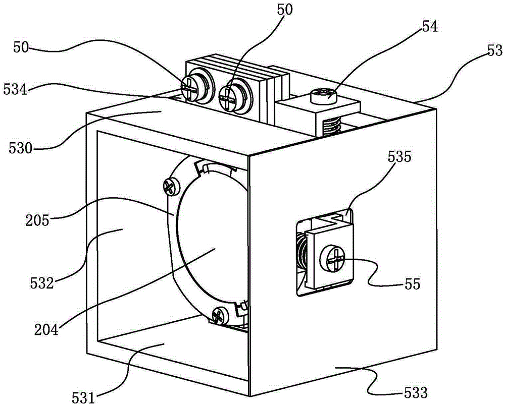
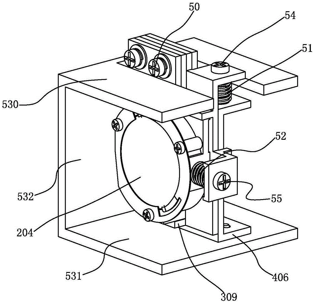
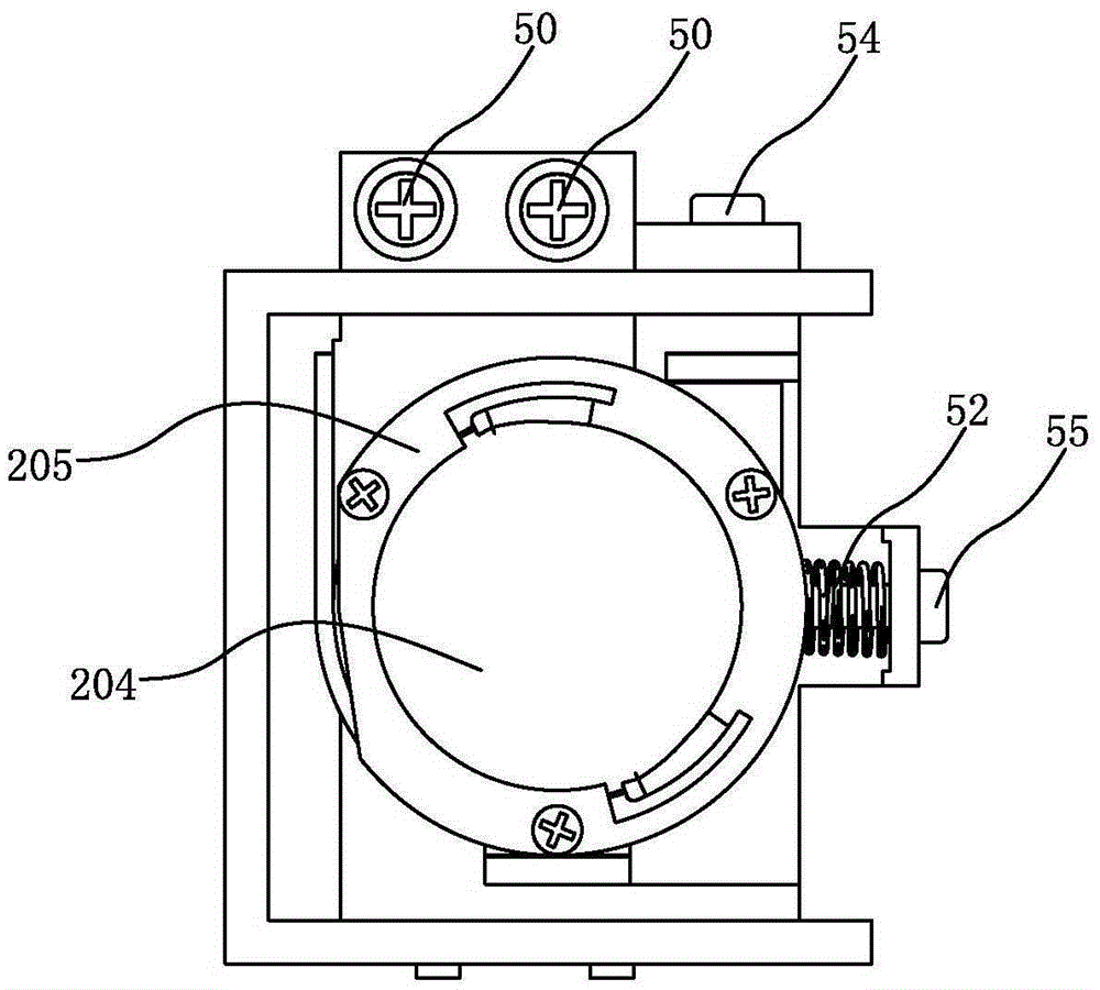
[0046] Such as Figure 1 to Figure 11 A lens adjustment device is shown, and the lens adjustment device includes: a first adjustment base 20, a second adjustment base 30 and a third adjustment base 40 placed in sequence; the first adjustment base 20 has The first hollow part 201, the first positioning component 202 arranged on the side wall of the first adjustment base 20, and the first positioning reference hole 203 arranged on the upper part of the first adjustment base 20; the lens 204 passes through the annular pressing piece 205 is tightly pressed and fixed with the first adjustment base 20, and the position of the lens 204 corresponds to the position of the hollow part; the second adjustment base 30 has a second hollow part 301, which is set on the second adjustment base The first bending part 302 on the side wall of the seat 30, the second bending part 303 arranged on the upper part of the second adjustment base 30, and the second positioning reference hole 304 arranged...


PUM


Abstract

The invention discloses a lens adjusting device and a projection optical system. The lens adjusting apparatus includes a first adjustment base, a second adjustment base and a third adjustment base which are arranged sequentially; the first adjustment base is provided with a first hollow part, a first positioning component arranged at the side wall of the first adjustment base, and first positioning datum holes located at the upper part of the first adjustment base; the second adjustment base is provided with a second hollow part, a first bending component arranged at the side wall of the second adjustment base, a second bending component arranged at the upper part of the second adjustment base, and second positioning datum holes located at the upper part of the second adjustment base; and the third adjustment base is provided with a third hollow part, a third bending component arranged at the upper part of the third adjustment base, and second positioning datum holes located at the upper part of the third adjustment base. With the lens adjusting device of the invention adopted, the consistency of the optical axis of the optical system can be ensured greatly.

Description

technical field [0001] The invention relates to an optical element adjustment device and an optical system with the optical element adjustment device, in particular to a lens adjustment device and a projection optical system. Background technique [0002] The optical system is a system composed of various optical elements in a certain order. It is generally used for imaging or optical processing. It can meet a series of requirements and obtain a high-quality optical system that meets the needs. It is not a simple combination of several optical elements. The parameters of each optical element must be reasonably configured and properly determined. As an important optical element in the optical system, the position accuracy of the lens has a great impact on the optical path directly. In the prior art, errors caused by optical path calculation, machining technology and assembly technology often cause The deviation of the optical system on the optical path further affects the pe...

Claims


Application Information

Patent Timeline
Patent Type & Authority Applications(China)
IPC IPC(8): G02B7/02G03B21/14
CPCG02B7/003G02B7/021G03B21/142
Inventor 杜健孔维成付瑶孙阳杨思文陈易
Owner CHINA HUALU GRP
Learn More