Mirror adjustment structure and projection optical system

A projection optical system and a technology for the optical system are applied in the field of an optical element adjustment structure and a projection optical system having such an optical element adjustment structure, and can solve the problems of small adjustment range, inability to fully guarantee the consistency of the optical axis, and lack of projected images. , to solve the machining accuracy and assembly errors, improve the optical path output effect, and achieve the effect of good optical axis consistency

Active Publication Date: 2018-04-27
CHINA HUALU GRP
View PDF6 Cites 0 Cited by
  • Summary
  • Abstract
  • Description
  • Claims
  • Application Information

AI Technical Summary

Problems solved by technology

The mirror adjustment method in the prior art is to directly adjust the screws arranged on the back plate of the mirror, which has defects such as inflexible operation, small adjustment range, and inability to see the adjustment state of the mirror. The errors caused by the process and other aspects often cause the deviation of the optical system on the optical path, which in turn affects the performance of the optical system, making the consistency of the optical axis of the entire optical system poor
[0003] A projector is a device that can project images or videos onto a screen. The key to determining the quality of projection often lies in the optical system of the projector. The projection optical system in the prior art has the following problems: the consistency of the optical axis cannot be completely guaranteed , causing loss of light energy, which may result in missing projected images

Method used


Image

  • Mirror adjustment structure and projection optical system
  • Mirror adjustment structure and projection optical system
  • Mirror adjustment structure and projection optical system

Examples


Embodiment Construction

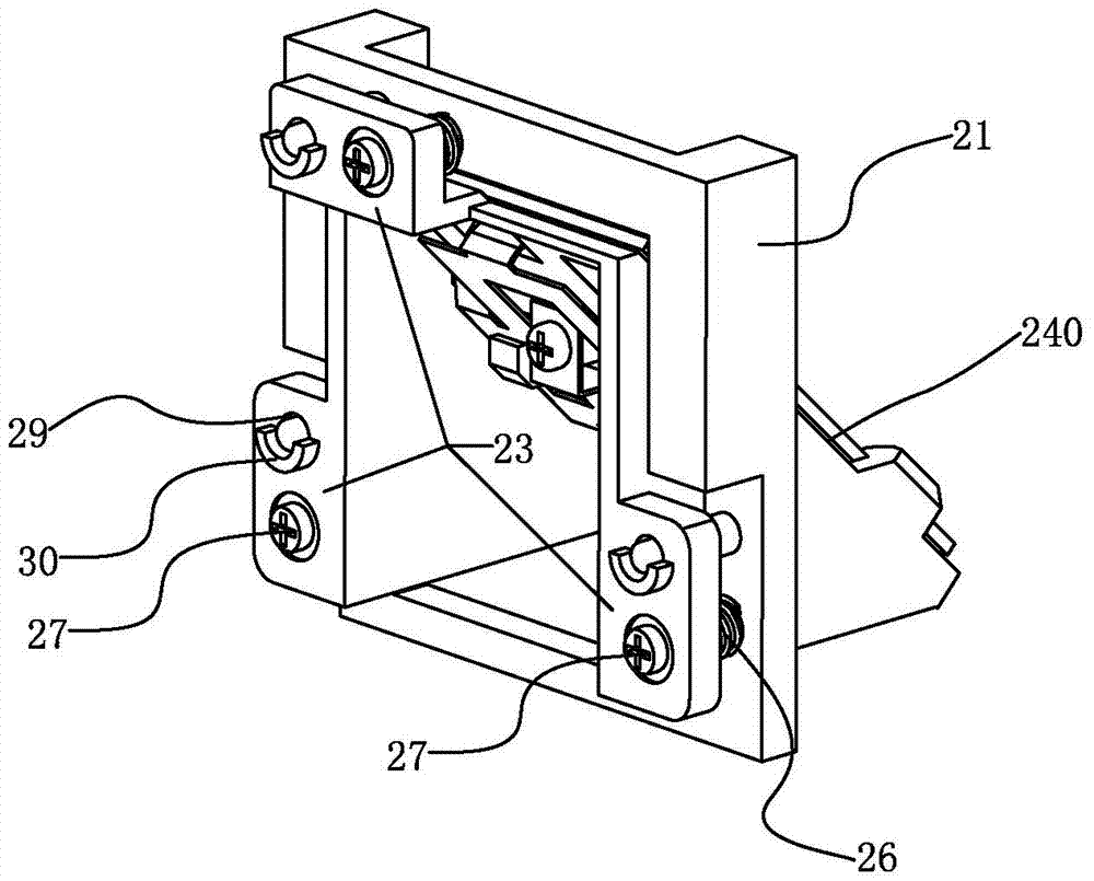
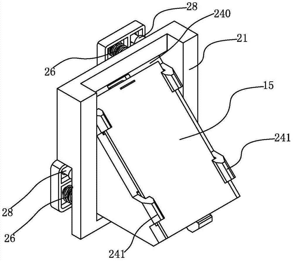
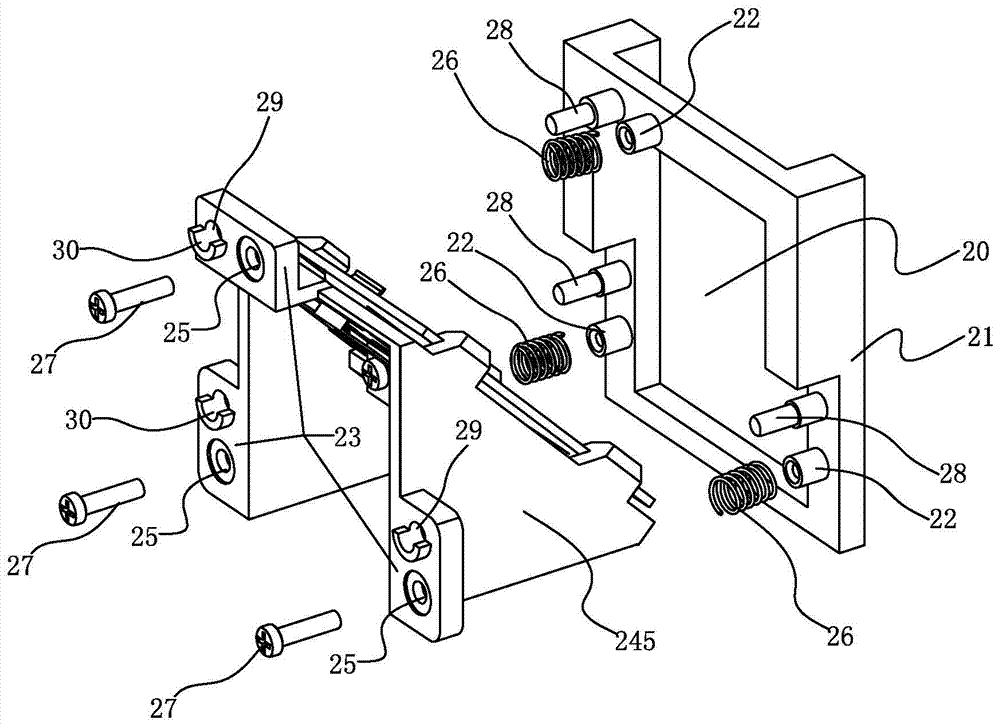
[0046] like figure 1 , figure 2 , image 3 , Figure 4 , Figure 5 , Image 6 , Figure 7 and Figure 8 A mirror adjustment structure shown includes: a base frame 21 with a hollow portion 20; three positioning components 22 are arranged on the base frame 21; a mirror base; The adjustment part 23 and the bearing part with the inclined surface 240 arranged opposite to the base frame 21; the reflector 15 is mounted on the inclined surface 240 in a detachable manner; the adjustment part 23 is opposite to the positioning part 22 An adjustment hole 25 is provided at the position; an adjustment spring 26 placed between the adjustment hole 25 and the positioning member 22; and a fastening member 27; when the inclined surface 240 passes through the hollow portion 20, through The fastening part 27 is connected to the positioning part 22 on the base frame 21 via the adjustment hole 25 on the adjustment part 23 and the adjustment spring 26; further, the three positioning parts 22 ...


PUM


Abstract

The invention discloses a reflection mirror adjustment structure and a projection optical system. The reflection mirror adjustment structure comprises: a basic frame with a hollow part; three positioning parts are arranged on the basic frame; a reflection mirror base; The mirror base includes an adjustment part opposite to the base frame and a bearing part with an inclined surface; the reflector is mounted on the inclined surface in a detachable manner; the adjustment part is opposite to the positioning part An adjustment hole is provided at the position; an adjustment spring placed between the adjustment hole and the positioning part; and a fastening part; when the inclined surface passes through the hollow part, the fastening part passes through the adjustment The adjustment hole on the part and the adjustment spring are connected with the positioning part on the base frame; the invention solves the problem of optical axis deviation caused by machining accuracy and assembly error, can improve the output effect of the optical path, and maintain the optical system Better optical axis consistency.

Description

technical field [0001] The invention relates to an optical element adjustment structure and a projection optical system with the optical element adjustment structure, in particular to a mirror adjustment structure and projection optical system. Background technique [0002] An optical system is a system composed of various optical elements in a certain order, and is generally used for imaging or optical information processing. It is not a simple combination of several optical components that can meet a series of requirements and obtain a desired high-quality optical system. It often requires a reasonable configuration and proper determination of the parameters of each optical component to achieve. Among them, the reflector is an optical element that works by the law of reflection, and is mainly used to change the direction of the optical path. There is a certain deviation, and then the reflectors in the optical system, especially the reflectors at some key positions, need t...

Claims


Application Information

Patent Timeline
Patent Type & Authority Patents(China)
IPC IPC(8): G02B7/182G03B21/20
CPCG02B7/1825G03B21/204G03B21/2066G03B21/208
Inventor 杜健孙阳杨思文孔维成付瑶陈易
Owner CHINA HUALU GRP
Why Eureka
Try Eureka