An automatic control device for cold water pressure in copper processing

An automatic control device and cold water technology, applied in the field of copper processing equipment, can solve problems such as adjustment errors and fluctuations, linear correlation of water pumps, unfavorable metallographic structure uniformity of copper rods, etc., to achieve accurate adjustment, simplified structure, and improved stability Effect

Active Publication Date: 2020-10-16
亳州易泽信息科技有限公司
View PDF8 Cites 1 Cited by
  • Summary
  • Abstract
  • Description
  • Claims
  • Application Information

AI Technical Summary

Problems solved by technology

The flow rate and temperature of the cooling water in the upward continuous casting crystallizer need to be strictly controlled, because different microscopic metallographic structures will be produced during the crystallization of molten copper liquid under different cooling conditions; when the temperature of the cooling water inlet is stable , the faster the flow rate of cooling water, the lower the water temperature at the water outlet; if the water temperature at the water outlet is too high, the cooling and crystallization of the copper rod will be incomplete, and the water temperature at the water outlet is too low, which is not conducive to the uniformity of the internal metallographic structure of the copper rod.
[0003] In the prior art, the water pressure is mainly adjusted by adjusting the power of the water pump, so as to control the flow rate of the cooling water, that is, the temperature of the water outlet. However, the power adjustment structure of the water pump is complicated, and the power of the water pump is not completely linearly related to the water pressure. , so there are large errors and fluctuations in the adjustment, which affects the stability of the production quality of the upward continuous casting machine

Method used


Image

  • An automatic control device for cold water pressure in copper processing

Examples


Embodiment Construction

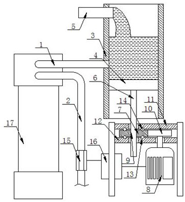
[0015] refer to figure 1 , figure 1 It is a schematic structural diagram of a specific embodiment of the present invention.

[0016] like figure 1 As shown, an automatic control device for cold water water pressure for copper processing includes a cooling water inlet pipe 1, a cooling water outlet pipe 2 and a cooling water storage tank 3, the cooling water inlet pipe 1 is connected to the cooling water storage tank 3; the cooling water The water storage tank 3 is provided with a liquid level adjustment piston 4 and a water storage input pipe 5, and the water storage input pipe 5 is located above the connection between the cooling water inlet pipe 1 and the cooling water storage tank 3. The surface adjustment piston 4 is located below the connection between the cooling water inlet pipe 1 and the cooling water storage tank 3, the bottom of the liquid level adjustment piston 4 is connected to the piston drive connecting rod 6, and the bottom of the piston drive connecting rod ...


PUM


Abstract

The invention discloses a copper processing cooling water pressure automatic control device, comprising a cooling water inlet pipe, a cooling water outlet pipe and a cooling water storage tank, wherein the cooling water inlet pipe is communicated with the cooling water storage tank, the cooling water storage tank is internally provided with a liquid level adjusting piston and a water storage inputpipe, the water storage input pipe is located above a joint between the cooling water inlet pipe and the cooling water storage tank, the liquid level adjusting piston is located below the joint between the cooling water inlet pipe and the cooling water storage tank, the bottom of the liquid level adjusting piston is connected to a piston driving connecting rod, and the bottom of the piston driving connecting rod extends out of the cooling water storage tank and is in transmission connection with a lifting drive mechanism. The copper processing cold water pressure automatic control device canrealize the linear correlation adjustment of cooling water pressure, thereby ensuring the accurate adjustment of cooling water pressure, improving the stability of production quality of an upward continuous casting machine. A water pressure regulation system has a simplified structure.

Description

technical field [0001] The invention relates to the technical field of copper processing equipment, in particular to an automatic control device for cold water water pressure for copper processing. Background technique [0002] The upward lead continuous casting machine is a large-length bright oxygen-free copper rod production equipment, which has the advantages of high production efficiency and good production continuity; the upward lead continuous caster is mainly composed of raw copper melting furnace, upward lead continuous casting crystallization in structure The continuous casting crystallizer sucks the molten copper liquid in the melting furnace through vacuum negative pressure, and then crystallizes the molten copper liquid into solid copper through the rapid cooling of the cooling water channel, so as to obtain large-length bright Oxygen-free copper rod. The cooling water flow rate and temperature in the upward continuous casting mold need to be strictly controlle...

Claims


Application Information

Patent Timeline
Patent Type & Authority Patents(China)
IPC IPC(8): B22D11/055B22D11/14B22D11/22
CPCB22D11/055B22D11/22
Inventor 尚成荣
Owner 亳州易泽信息科技有限公司
Why Eureka
Try Eureka