

Touch identification method and display apparatus based on infrared touch screen
An infrared touch screen and display device technology, applied in the input/output process of data processing, instruments, electrical and digital data processing, etc., can solve problems such as failure, inaccurate touch of touch points, etc., to shorten the time required and improve the response. Speed, accurate touch point effect
- Summary
- Abstract
- Description
- Claims
- Application Information
AI Technical Summary
Problems solved by technology
Method used
Image

Examples
Embodiment 1
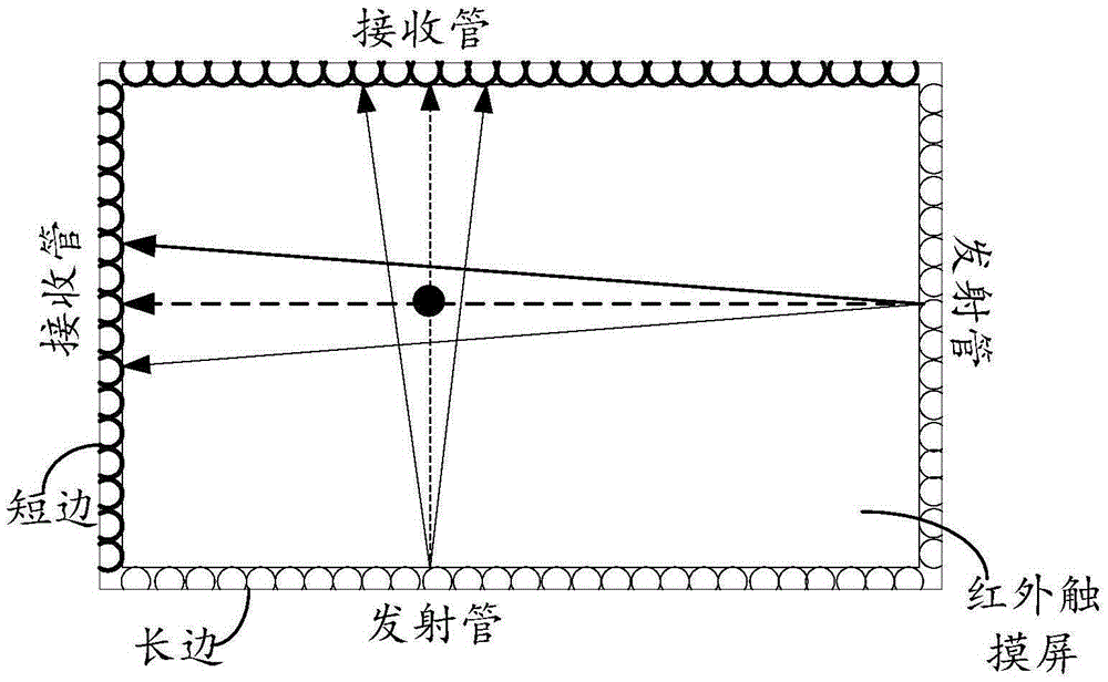
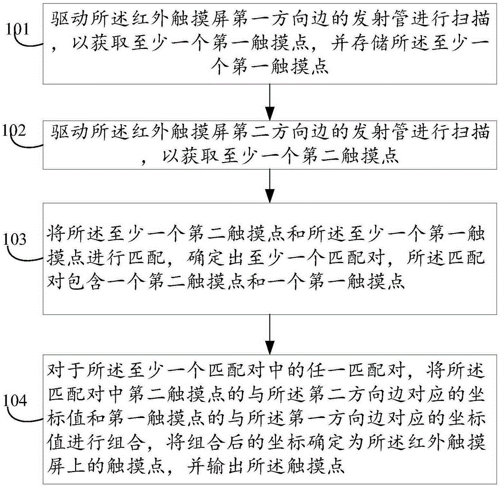
[0040] image 3 The touch recognition method based on an infrared touch screen provided by an embodiment of the present invention is applied to a display device including an infrared touch screen, such as figure 1 As shown, an infrared touch frame is set on an ordinary liquid crystal display, and the infrared touch frame includes a long-side emitting tube, a short-side emitting tube, a long-side receiving tube, and a short-side receiving tube, and the long-side transmitting tube and the long-side receiving tube are arranged relatively , the short-side transmitting tube and the short-side receiving tube are set relative to each other, such as image 3 As shown, the method may include:
[0041] Step 101: Scan the emission tube on the first side of the infrared touch screen to obtain at least one first touch point, and store the at least one first touch point.
[0042] Wherein, during the scanning process of the emission tube on the side of the first direction, the angle and sc...
Embodiment 2
[0077] Figure 7 A structural diagram of a display device 100 provided for an embodiment of the present invention, such as Figure 7 As shown, the display device 100 may include: an infrared touch screen 1011, an acquisition unit 1012, a storage unit 1013, a matching unit 1014, a determination unit 1015, and an output unit 1016;
[0078] Wherein, the infrared touch screen 1011 is figure 1 The rectangular structure shown includes a liquid crystal display and an infrared touch frame arranged around the liquid crystal display, the infrared touch frame includes a long-side emitting tube, a short-side emitting tube, a long-side receiving tube, and a short-side receiving tube, The long-side transmitting tube and the long-side receiving tube are arranged oppositely, and the short-side transmitting tube and the short-side receiving tube are arranged oppositely; the user's touch operation on or near it can be collected (for example, the user uses any suitable object or accessory such ...
PUM
 Abstract
Description
Claims
Application Information