Multi-wire cutting machine

A technology of multi-wire cutting machine and cutting area, applied in the direction of working accessories, fine working devices, stone processing equipment, etc., can solve the problems of long time required for cutting silicon rods, low cutting efficiency, and small number of silicon rods, etc., to achieve The effect of improving quality, improving cutting efficiency and reducing production cost

Active Publication Date: 2012-10-17
LESHAN TOPRAYCELL
View PDF8 Cites 5 Cited by
  • Summary
  • Abstract
  • Description
  • Claims
  • Application Information

AI Technical Summary

Problems solved by technology

[0002] At present, silicon wafers used for solar cells are mostly produced by multi-wire cutting machines. The existing multi-wire cutting machines include a frame, steel wires, and two wire rollers arranged in parallel on the frame. An annular wire groove, the steel wire is set in the annular wire groove and passed around two wire rollers successively to tighten, the area between the two wire rollers is the cutting area, and the center distance between the two wire rollers is 600mm, due to the two wire rollers The distance between the wire rollers is longer, so that the span of the cutting area is larger. Therefore, the multi-wire cutting machine can cut two silicon rods at the same time, and the two silicon rods are arranged side by side. However, although this multi-wire cutting machine can simultaneously Cutting two silicon rods, however, the larger span of the cutting area will bring some other problems, for example, when cutting silicon rods, the bow height of the steel wire is relatively large, about 10mm, and the steel wire will be affected when cutting silicon rods. The force of pressing down the silicon rod, and then deviate from the original position. The w

Method used


Image

  • Multi-wire cutting machine

Examples


Example Embodiment

[0014] The present invention will be further described below in conjunction with the drawings.

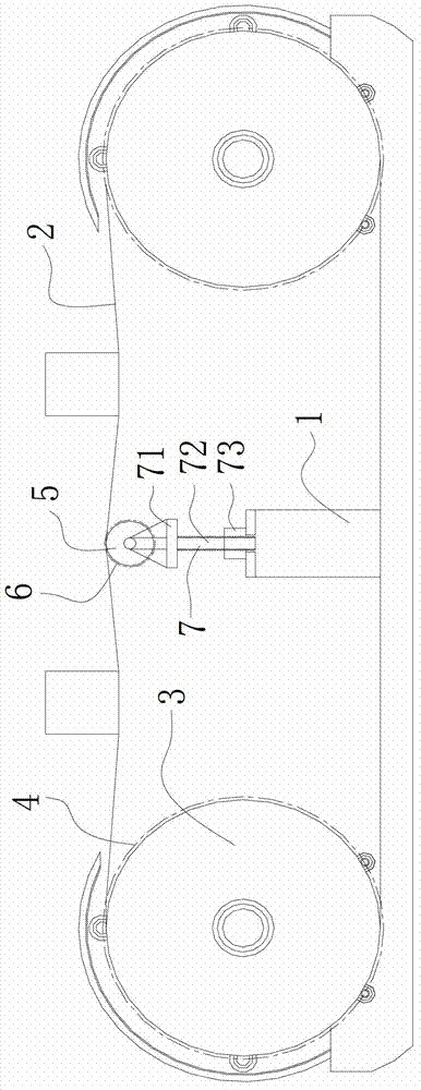
[0015] Such as figure 1 As shown, the multi-wire cutting machine includes a frame 1, a metal wire 2 and two wire rollers 3 arranged in parallel on the frame 1. The surface of the wire roller 3 is provided with a plurality of annular wire grooves 4, and the metal wire 2 is arranged in In the annular wire groove 4 and successively bypassing two wire rollers 3, the area between the two wire rollers 3 is a cutting area, and an auxiliary supporting roller for supporting the metal wire 2 is arranged between the two wire rollers 3 5. The auxiliary support roller 5 divides the cutting into two sub-cutting areas. By setting the auxiliary support roller 5 for supporting the metal wire 2 between the two wire rollers 3, the auxiliary support roller 5 is used to divide the cutting into two sub-cutting areas. Each sub-cutting area independently cuts a silicon rod. Compared with the entire cutting...


PUM

PropertyMeasurementUnit
Diameteraaaaaaaaaa

Abstract

The invention discloses a multi-wire cutting machine capable of reducing height of a wire bow. The multi-wire cutting machine comprises a machine frame, metal wires and two wire rollers arranged on the machine frame in parallel. The surface of each wire roller is provided with a plurality of annular wire grooves, the metal wires are arranged in the annular wire grooves and successively bypasses the two wire roller to be tightened, and an auxiliary supporting roller for supporting the metal wires is arranged between the two wire rollers. The auxiliary supporting roller for supporting the metal wires is arranged between the two wire rollers, thereby greatly reducing height of the wire bow of the metal wire, further reducing cutting distance of a silicon rod, shortening required time in cutting the silicon rod, and improving cutting efficiency. Moreover, the number of silicon rods cut by one metal wire can be greatly increased, usage amount of the metal wires is reduced, and production cost is lowered. Besides, line marks left on cut silicon piece surfaces by the metal wires can be greatly reduced, thereby improving quality of silicon pieces. The multi-wire cutting machine is suitable for being popularized and applied to the cutting equipment field.

Description

technical field [0001] The invention relates to the field of cutting equipment, in particular to a multi-wire cutting machine for cutting silicon rods into silicon wafers. Background technique [0002] At present, silicon wafers used for solar cells are mostly produced by multi-wire cutting machines. The existing multi-wire cutting machines include a frame, steel wires, and two wire rollers arranged in parallel on the frame. An annular wire groove, the steel wire is set in the annular wire groove and passed around two wire rollers successively to tighten, the area between the two wire rollers is the cutting area, and the center distance between the two wire rollers is 600mm, due to the two wire rollers The distance between the wire rollers is longer, so that the span of the cutting area is larger. Therefore, the multi-wire cutting machine can cut two silicon rods at the same time, and the two silicon rods are arranged side by side. However, although this multi-wire cutting m...

Claims


Application Information

Patent Timeline
IPC IPC(8): B28D5/04B28D7/00
Inventor 陈五奎李军陈辉耿荣军徐文州冯加保
Owner LESHAN TOPRAYCELL
Why Eureka
Try Eureka