Chucks and machine tools

A chuck and jaw technology, which is applied to chucks, turning equipment, tool holder accessories, etc., can solve the problems of small diameter range, poor synchronization of jaws, and small working stroke range of chucks, so as to improve the accuracy of fixtures. Effect

Active Publication Date: 2017-12-12
浙江今飞机械有限公司
View PDF9 Cites 0 Cited by
  • Summary
  • Abstract
  • Description
  • Claims
  • Application Information

AI Technical Summary

Problems solved by technology

[0002] Chucks are commonly used fixtures on machine tools. Most of the existing chucks are driven by spiral grooves. The spiral grooves are set on the bevel gear. The chuck seat is equipped with radial chute, and the jaws of the chuck are installed in the radial chute. , and the bottom of the claw is equipped with a slider that matches the spiral groove. The expansion and contraction of the cylinder or hydraulic cylinder drives the rotation of the bevel gear, and the spiral groove on the bevel gear drives the claw to move along the radial chute. The distance of radial movement is much smaller than the telescopic distance of air cylinder or hydraulic cylinder, resulting in a small working stroke range of the chuck. Therefore, the diameter range of parts that can be clamped by this chuck is small, and the synchronization of each claw of the spiral groove drive is poor.

Method used


Image

  • Chucks and machine tools
  • Chucks and machine tools

Examples


Embodiment Construction

[0031] In order to understand the above-mentioned purpose, features and advantages of the present invention more clearly, the present invention will be further described in detail below in conjunction with the accompanying drawings and specific embodiments. It should be noted that, in the case of no conflict, the embodiments of the present application and the features in the embodiments can be combined with each other.

[0032] In the following description, many specific details are set forth in order to fully understand the present invention. However, the present invention can also be implemented in other ways than described here. Therefore, the protection scope of the present invention is not limited by the specific implementation disclosed below. Example limitations.

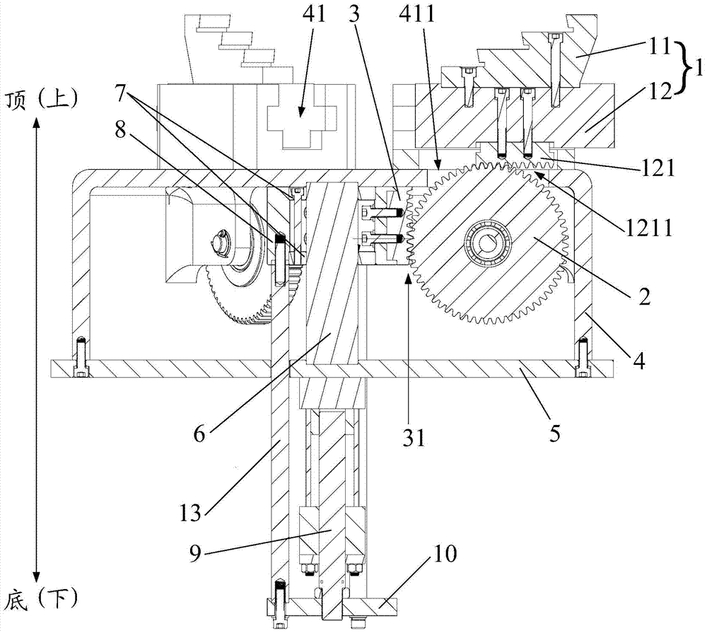
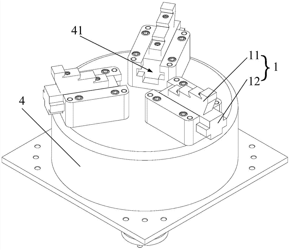
[0033] Such as figure 1 and figure 2 As shown, the specific embodiment of the first aspect of the present invention provides a three-jaw chuck, including: a mounting seat 4; three claws 1 uniformly arrange...


PUM


Abstract

The invention provides a chuck and a machine tool. The chuck comprises multiple claws, transmission gears and a driving device, wherein the bottom of each claw is provided with first teeth; the number of the transmission gears is equal to that of the claws, and the transmission gears are meshed with the first teeth respectively; second teeth are arranged on the driving device and meshed with all the transmission gears and can drive the claws to move through the transmission gears. The chuck provided in the scheme is large in work stroke range, the claws are high in synchronism, and the chuck is simple in part structure, low in production cost, easy to install and operate, convenient to repair and low in weight.

Description

technical field [0001] The invention relates to the field of mechanical processing, and more specifically, to a chuck and a machine tool with the chuck. Background technique [0002] Chucks are commonly used fixtures on machine tools. Most of the existing chucks are driven by spiral grooves. The spiral grooves are set on the bevel gear. The chuck seat is equipped with radial chute, and the jaws of the chuck are installed in the radial chute. , and the bottom of the claw is equipped with a slider that matches the spiral groove. The expansion and contraction of the cylinder or hydraulic cylinder drives the rotation of the bevel gear, and the spiral groove on the bevel gear drives the claw to move along the radial chute. The distance of radial movement is much smaller than the telescopic distance of air cylinder or hydraulic cylinder, resulting in a small working stroke range of the chuck. Therefore, the diameter range of parts that can be clamped by this chuck is small, and th...

Claims


Application Information

Patent Timeline
Patent Type & Authority Patents(China)
IPC IPC(8): B23B31/169
CPCB23B31/16104
Inventor 傅成陆云德朱正元
Owner 浙江今飞机械有限公司
Why Eureka
Try Eureka